Estación meteorológica remota Raspberry Pi Pico W (alimentada por energía solar)
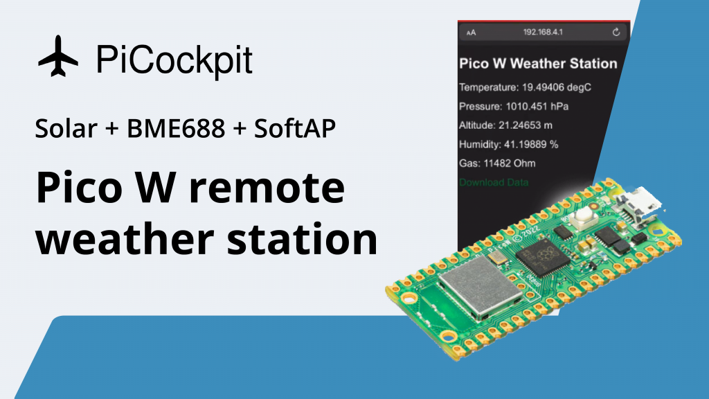
Una característica muy especial en el Raspberry Pi Pico W es la función SoftAP.
SoftAP significa punto de acceso habilitado por software, lo que le permite transmitir una red WiFi directamente desde la Raspberry Pi Pico W.
Por eso hemos decidido hacer este proyecto con energía solar.
Cómo un proyecto de energía solar se cruza con SoftAP
Esta es la cuestión.
Si quisieras crear un proyecto que midiera datos lejos de tu casa, te encontrarías con que no podrás obtener esos datos de forma inalámbrica.
En este caso, también podrías usar el Pico normal, ya que no podrás utilizar su capacidad inalámbrica.
Un proyecto con energía solar es probablemente uno de ellos, dado que hay que colocarlo en una zona expuesta al sol, que suele ser al aire libre.
Aquí es donde entra SoftAP. Digamos que quieres saber qué tiempo hace fuera. A continuación, conectarse a la SoftAP que la Raspberry Pi Pico W está transmitiendo, y luego entrar en la dirección IP que muestra los datos.
Este es más o menos el mejor escenario de cómo podemos explotar las ventajas de la Raspberry Pi Pico W.
Es decir, es posible comprar un complemento LTE o un complemento inalámbrico de largo alcance, pero entonces no sería realmente un tutorial de Pico W, ya que podrías usar esos componentes en el Pico normal.
¿Qué pasa con Bluetooth en la Raspberry Pi Pico W?
Sería genial si pudiera utilizar Bluetooth, pero a partir de la fecha de publicación de este tutorial, Bluetooth no está habilitado en la Raspberry Pi Pico W.
El 1 de julio de 2022, Raspberry Pi Engineer & Forum Moderator jamesh dijo que, "Ya hemos empezado a trabajar en el software para BT, no hay calendario que pueda ofrecer todavía. El software necesita ser escrito probado, y tutoriales escritos".
Piezas

- Raspberry Pi Pico W
- Panel solar 6V
- Módulo de carga USB-C TP4056
- NR18650 Batería de iones de litio de 3,6 V
- Placa de interconexión BME688
- Portapilas para tipo 18650
- Diodo Schottky
- Cabezales para Pico W y BME688
- Tablero de pruebas
Actualiza el firmware de tu Raspberry Pi Pico W
El firmware de la Raspberry Pi Pico W sigue evolucionando constantemente por lo que sería mejor utilizar el firmware más reciente. Por ejemplo, el primer MicroPython UF2 público para la Pico W tiene algunos problemas con la seguridad, ya que las redes están siempre abiertas.
Siga este enlace para saber cómo actualizarlo. El enlace también te mostrará un método rápido para difundir tu propia red WiFi.
Instalación solar
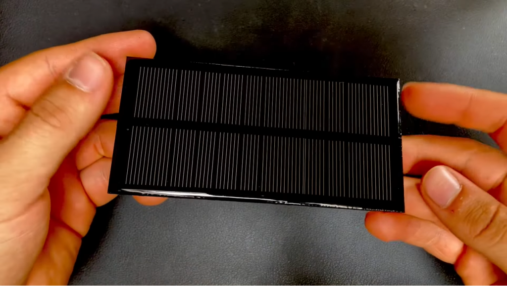
El panel solar debe producir al menos 6 voltios y 150 mA.
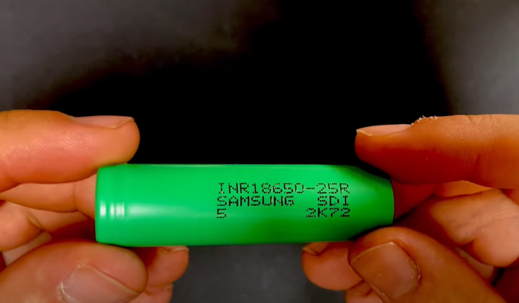
La batería debe ser una batería de litio de la serie 18650 con una tensión nominal de 3,7 V.
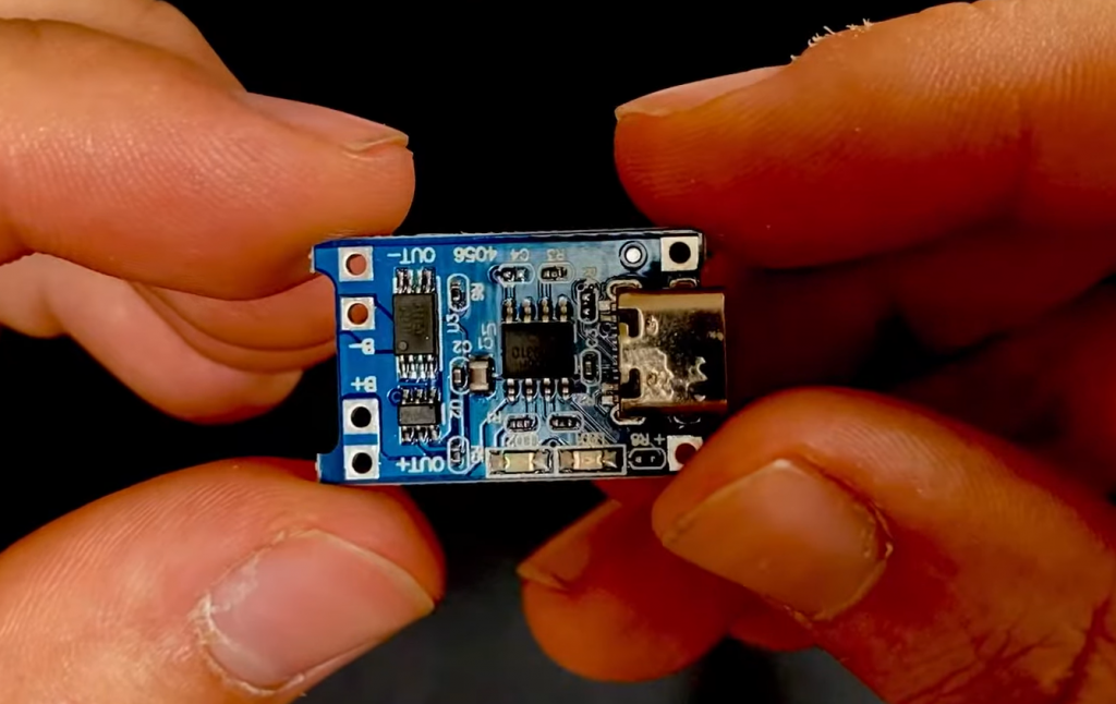
El módulo TP4056 protegerá la batería y alimentará el Pico W.
Dispositivo de seguimiento meteorológico
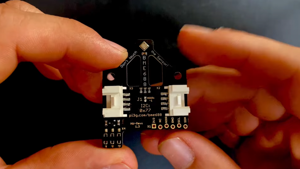
Para este proyecto, utilizamos nuestro Placa de interconexión BME688 de diseño propio.
Puedes usar cualquier sensor meteorológico como un DHT11 o DHT22, pero el código y cableado de este artículo está realmente pensado para un BME688.
Cableado
Coloca tu Pico W y tu BME688 en una protoboard.
Hay cuatro pines que necesitas conectar: 3.3V, GND, SCL y SDA en el BME688.
Esto es lo que usamos:
Pico W's GP1 se conecta a SCL;
GP0 se conecta a SDA;
GND se conecta a GND;
Estos tres pines deben estar en línea, junto a la ranura micro-USB.
3V3 se conecta a 3V3que se encuentra al otro lado del tablero.
Módulo de carga USB-C TP4056
Tendrás que soldar cables en el TP4056.
Es una buena práctica soldar los cables rojos a las conexiones positivas y los negros a las negativas.

Los pines al lado del conector USB-C son para una conexión de alimentación externa, como nuestro módulo solar.
Conecta estas clavijas a tu panel solar.
En el otro lado, hay pines destinados a la salida de potencia. Los pines etiquetados como B+ y B- deben conectarse a la batería.
Hemos decidido utilizar pinzas para conectar nuestro portapilas al TP4056 por si necesitamos cambiar el circuito, pero puedes soldar el portapilas directamente al TP4056 si lo deseas.
Diodo Schottky

Conecta un diodo Schottky al pin VSYS del Pico W.
Asegúrate de que el anillo gris del diodo está orientado hacia el Pico W y de que el otro extremo está conectado al carril positivo de la protoboard.
Dado que estamos alimentando el Pico con dos entradas de alimentación, USB y el sistema solar, necesitamos utilizar un diodo Schottky.
Un diodo Schottky evita la retroalimentación y permite utilizar dos tensiones. Más información aquí.
Conecta el TP4056 a la protoboard

Conecta la salida positiva del TP4056 al carril positivo de la protoboard, donde se encuentra el diodo Schottky.
A continuación, conecta la salida negativa del TP4056 a un pin negativo de la Raspberry Pi Pico W.
Código para ejecutar la estación meteorológica Raspberry Pi Pico W
Hemos subido todo nuestro código a nuestro Github repo aquí.
Aquí está una guía sobre cómo cargar archivos en tu Pico W.
Si ha conectado los componentes como se ha escrito anteriormente, podrá ejecutar el código sin ningún cambio.
Dicho esto, aquí tienes algunas cosas que quizá quieras cambiar.
bme68x.py
Este script modifica la salida del BME688.
Para obtener lecturas precisas de temperatura y altitud, deberá modificar estas líneas, resaltadas en negrita:
 # change this to match the location's pressure (hPa) at sea level
        # bme68x.sea_level_pressure = 1013.25
       <strong> self.bme68x.sea_level_pressure = 1013</strong>

        # You will usually have to add an offset to account for the temperature of
        # the sensor. This is usually around 5 degrees but varies by use. Use a
        # separate temperature sensor to calibrate this one.
        <strong>self.temperature_offset = -9</strong>
main.py
El archivo main.py lanza un punto de acceso y también ejecuta un servidor que entrega un archivo HTML a cualquiera que se conecte.
El archivo HTML es donde puedes ver las lecturas del BME688.
Al recibir una conexión (vía sockets), el Pico W enviará el archivo index.html, pero antes de enviarlo, reemplazará algunas cadenas con los datos tomados del BME688, a través de este bloque de código:
data = {
    'T': 0,
    'P': 0,
    'A': 0,
    'H': 0,
    'G': 0,
    }
...
def get_html(html_name):
    with open(html_name, 'r') as file:
        html = file.read()

    return html
...
sensor = bme68x.BME68X()
...
response = get_html('index.html')
    data = sensor.save_data('data.json')
    blink_onboard_led(1, 0.2)
    response = response.replace('id_temp', str(data['T']))
    response = response.replace('id_pres', str(data['P']))
    response = response.replace('id_alti', str(data['A']))
    response = response.replace('id_humi', str(data['H']))
    response = response.replace('id_gas', str(data['G']))
    print_data(data)
    conn.send(response)
    conn.close()
Como puede ver, la línea donde dice datos = sensor.guardar_datos('datos.json') es donde obtenemos los datos del sensor, y luego el código modifica el archivo HTML con las lecturas correctas de temperatura, presión, altitud, humedad y conductividad del gas.
Hay una actualización automática cada tres segundos.
El siguiente es el bloque de código necesario para transmitir el punto de acceso en la Raspberry Pi Pico W:
essid = 'Pico-W-Weather-Station'
password = '#FreeThePicoW'

ap = network.WLAN(network.AP_IF)
ap.active(True)
ap.config(essid=essid, password=password)

while ap.active() == False:
    pass

print('Connection successfull')
print(ap.ifconfig())

# Create sensor object
sensor = bme68x.BME68X()

s = socket.socket(socket.AF_INET, socket.SOCK_STREAM)
s.bind(('', 80))
s.listen(3)
blink_onboard_led(3, 0.2)
Nota: si estás usando el firmware original, debes actualizarlo o no podrás renombrar el SSID o tener seguridad inalámbrica. Lo probamos en la nightly build del 15 de julio de 2022 y finalmente funcionó. Hay algunas peculiaridades y errores más, así que asegúrate de leer nuestro tutorial aquí.
PULSE AQUÍ: Difusión de una red WiFi (punto de acceso SoftAP)
Conexión a su punto de acceso Pico W
Cuando el AP emita correctamente, su Pico W parpadeará tres veces con el código proporcionado.
Conéctese a su AP, que debería llamarse Estación Pico-Weather.
Escriba la contraseña #FreeThePicoW
Conéctese a su Pico utilizando la dirección IP. Si lo ejecuta desde Thonny, verá la dirección IP en el intérprete de comandos.
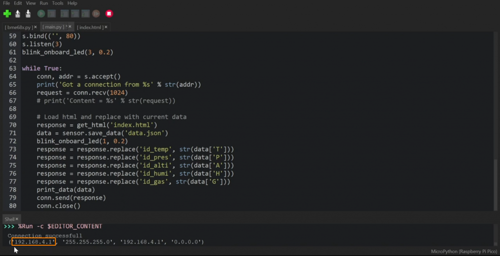
Si no, puede intentar 192.168.4.1 ya que esto es más comúnmente la dirección IP del Pico W y usted debe ver la captura de pantalla a la derecha:
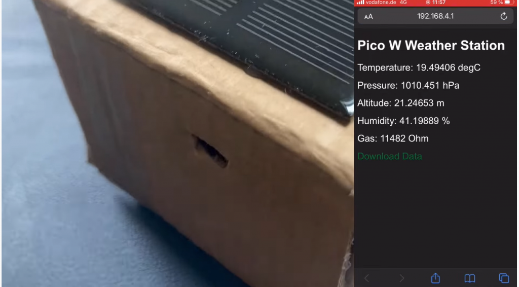
Has terminado.
En este proyecto, aprendiste cómo transmitir una red desde la función SoftAP del Raspberry Pi Pico W. También ha aprendido a conectar un panel solar y una batería al Pico W.
Si quieres saber más sobre el Pico W, ¿por qué no leer nuestro megaartículo aquí?
PULSE AQUÍ: Todo lo que necesitas saber sobre la Raspberry Pi Pico W
Especificaciones de TP4056 dice para mantener la entrada de tensión en 5,5 V o 6V, panel solar de 6V puede dar 6V y probablemente 7V + en algunos casos. Estoy confundido acerca de este extremo. ¿Podría aclararlo?
Gracias.
He hecho este proyecto y tuvo algunos grandes resultados lecturas muy precisas. Pero han golpeado un problema que sólo funciona durante unos 10 2 15 minutos y luego se detiene. He encontrado que si elimino el archivo json es la única manera de conseguir que vuelva a funcionar de nuevo
¿Hay alguna forma de evitar que los almacene y sólo envíe datos
Tengo que decir, sin embargo, buen trabajo que sigan viniendo plz👍
En el archivo bme68x.py el método save_data sigue añadiendo líneas al archivo Jason. En algún momento debe estar haciéndose demasiado grande. Usted puede modificar para mantener sólo las últimas x líneas de data_list antes de guardar el archivo. usted tendrá que averiguar tue ideal x. También podría mantener la medición actual solamente. De esta manera el archivo se mantendrá lo suficientemente pequeño.
Después de 4.104 caracteres el 'data.json' llena la memoria del pequeño pico.-/
La pregunta es: ¿Cómo limitar esto para conseguir que el proyecto anterior tenga un acabado funcional?
¡Un ejemplo / código añadido (como una actualización) sería muy apreciado!
TiA - y que siga el buen trabajo.. .
PD: también se ha publicado una Issue correspondiente en la GitHub Repo.
Utilizar el TP 4056 para un proyecto de este tipo no es una solución eficaz, véase:
https://www.best-microcontroller-projects.com/tp4056.html
Diseño constructivo tal vez utilizando un MPTT Set Switch, como el Waveshare,
Describa aquí:
https://www.waveshare.com/solar-power-manager.htm
¡Salud!
¡Gran idea de proyecto! ¿Alguien ha diseñado una carcasa impresa en 3D que quiera compartir?
Hola,
gracias por el manual.
Según especificaciones TP4056 LED-Anzeige Rot: (Ladevorgang), LED-Anzeige Blau: (Standby, Ladevorgang abgeschlossen)
En mi caso tengo ambos LEDs encendidos en TP4056 cuando el panel solar se coloca bajo la luz directa. ¿Es eso lo que se pretende?
¿Es posible que la batería se pueda cargar con energía solar y suministrar energía a Pico simultáneamente?