Raspberry Pi Pico Video-Ausgang
TL;DR
Der Raspberry Pi Pico ist ein unglaublich kleiner Mikrocontroller. Er hat zwar keine integrierte Videoausgangsschnittstelle, wie seine größeren Geschwister Raspberry Pi Zero / 1 / 2 / 3 / 4 / 400 (HDMI / Doppel-HDMI in ihrem Fall), es ist möglich, dem Pico einen Videoausgang hinzuzufügen! (Als VGA oder DVI über einen HDMI-Anschluss, lesen Sie weiter für Details)
In diesem Beitrag erklären wir, warum ein Videoausgang eine ganz besondere Funktion für Mikrocontroller ist und welche Arten von Videoausgängen Sie für Ihren Pico bauen oder kaufen können. Außerdem zeigen wir Ihnen einen Beispielcode, der bereits vorkompiliert ist, so dass Sie ihn direkt herunterladen können, und wir werden darüber sprechen, was Sie ändern müssen, damit er läuft.
Unser Schwestergeschäft, buyzero.deverkauft eine Vielzahl von Pico-Zubehör - darunter die DVI-Sockeund die VGA-Trägerkarte für den Pico.
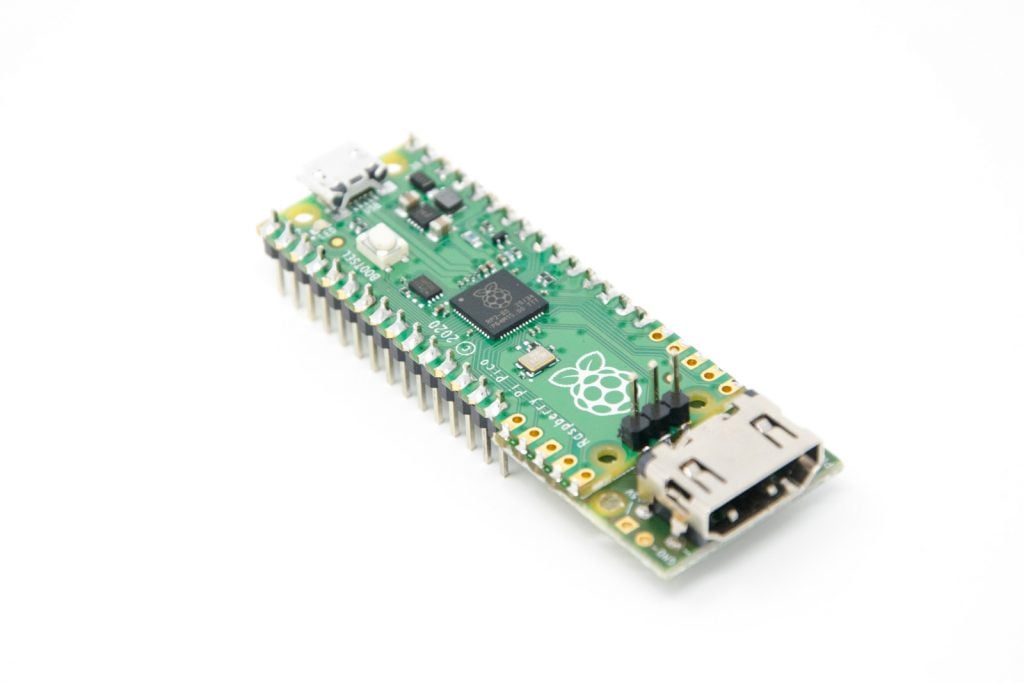
Hinweis: Der Pico verfügt nicht über ein Linux-Betriebssystem wie der Raspberry Pi Zero W zum Beispiel. Du wirst also wahrscheinlich etwas tiefer in die Programmierung eintauchen und deine Anwendungen auf den Pico hochladen müssen. Wenn das nicht dein Ding ist, der Pi Zero W könnte besser geeignet sein, um mit dem Spielen zu beginnen 🙂
Wenn Sie Ihr eigenes Videoprojekt mit dem Raspberry Pi Pico erfolgreich durchgeführt haben, lassen Sie es uns in den Kommentaren wissen!
Warum ist das Hinzufügen eines Raspberry Pi Pico Videoausgangs eine Herausforderung?
Der Raspberry Pi 400zum Beispiel basiert auf dem BCM2711 SoC. Dieses System-on-a-Chip verfügt über spezialisierte Hardware, die sich um die Videoausgabe kümmert und sie perfekt in dem Format aufbereitet, das für die jeweilige(n) Videoschnittstelle(n) spezifiziert ist, zwei HDMI-Ports im Fall des Pi 400. Außerdem verfügt er über einen riesigen Speicher (4 GB), in dem die Videoausgangsdaten gespeichert werden können.
Um dies besser zu verstehen, müssen wir uns einige Grundlagen der Computer-Videoausgabe ansehen:
Videoanzeige und -übertragung
Wir sehen die Anzeige auf dem Bildschirm "auf einmal". Unser Gehirn hat eine massiv parallele Verdrahtung, bei der es Informationen von allen verfügbaren Netzhautzellen (Zapfen- und Stäbchenzellen) auf einmal aufnimmt.

Foto von Karina Woroschejewa auf Unsplash
(* Der Mechanismus der Übertragung ins Gehirn integriert die Informationen über mehrere Netzhautzellen hinweg, aber es bleibt die Tatsache, dass viele Informationen parallel übertragen werden. Blick in bipolare Zellen wenn Sie mehr wissen wollen)
Das Gehirn hat jedoch Latenzen - es ist nicht in der Lage, die Änderungen bei visuellen Reizen schneller als 13 ms. (das ist etwa 1 zu 75 Bildern pro Sekunde).
Für uns bedeutet das, dass wir, wenn wir eine wirklich flüssige Animation zeigen wollen, etwa 60 verschiedene statische Bilder pro Sekunde zeigen müssen. Unser Gehirn wird diese statischen Bilder als flüssige und lebensechte Wiedergabe interpretieren.
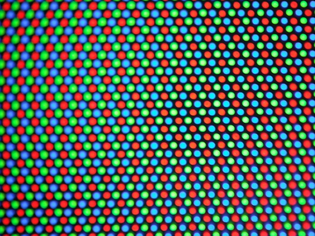
In der Regel sollen diese Bilder in Farbe sein.
Wir haben drei verschiedene Fotorezeptoren für Farben, also zeigt der Bildschirm nur diese drei verschiedenen Farben mit unterschiedlicher Helligkeit an. Auch hier wird unser Gehirn die dazwischen liegenden Farben aus den erhaltenen Informationen synthetisieren. (Am Rande bemerkt, lila existiert nicht wirklich als eigene Wellenlänge - es ist eine Mischung aus Rot und Blau).
Es gibt drei Grundfarben:
- rot
- grün
- blau
Zusammen sind sie bekannt als RGB. Wenn man alle drei addiert, erhält man Weiß. Wenn man Rot zu Grün addiert, erhält man Gelb, wenn man Grün zu Blau addiert, erhält man Cyan, wenn man Blau zu Rot addiert, erhält man Magenta.
Was wir also wirklich ausgeben wollen, sind:
- drei verschiedene Farben,
- jeweils mit einem anderen Helligkeitswert
- idealerweise etwa 60 verschiedene Werte pro Sekunde (60 Hz)
- eine bestimmte Bildschirmauflösung - z. B. 640 x 480
Berechnen wir, wie viele Daten dies pro Sekunde sind:
- 3 Farben
- x 8 Bit Farbtiefe
- x 60
- x 640 x 480
= 442.368.000 Bits pro Sekunde = ca. 422 MBit/s
(Man bedenke, dass z. B. die USB v1.1-Schnittstelle des Pico etwa 10 Mbit/s hat - etwa 40 Mal weniger Durchsatz!)
Um diese Informationen auszugeben, würden Sie sie idealerweise auch als Bitmap in Ihrem RAM halten wollen - ein Teil Ihrer Anwendung wird das Bild im RAM aktualisieren, während ein anderer sich darum kümmert, die Daten in einem Format zu liefern, mit dem ein Monitor arbeiten kann. Es muss sich dabei um RAM handeln, da wir mit hohen Geschwindigkeiten arbeiten und in der Lage sein müssen, diese Daten zuverlässig und mit geringen Latenzen zu lesen - was ein Flash-Speicher nicht bieten würde.
Lassen Sie uns berechnen, wie viel RAM wir benötigen:
- 640 x 480 (Auflösung)
- x 3 (Farben)
- x 8 Bits (Farbtiefe)
= 7372800 Bits = 900 kBytes (Anmerkung: 1 Byte = 8 Bits)
Während 900 kBytes um ein Vielfaches in den Arbeitsspeicher eines Raspberry Pi 400, der Pico hat nur 264KB RAM.
Wie Sie sehen, müssen wir einige der Parameter (z.B. Auflösung, Farbtiefe, ...) reduzieren, wenn wir eine Bitmap in den Arbeitsspeicher einpassen wollen, oder wir müssen uns etwas einfallen lassen, wie wir es hinbekommen, ohne alles zu speichern!
Der RP2040 PIO von Pico ermöglicht die Ausgabe von Videodaten
Während der Raspberry Pi 400 und andere Raspberry Pi-Modelle über spezielle Hardware-Schaltkreise verfügen, um all diese Informationen zu verarbeiten und zuverlässig auszugeben, verfügt der Pico nicht über spezielle Schaltkreise für die Videoausgabe.
Aber er hat einen Trick im Ärmel! Der RP2040 unterstützt PIO (programmable IO). Die PIO ist dafür gedacht, verschiedene Schnittstellen mit präzisem Timing zu emulieren, und sie ist sehr, sehr leistungsfähig! Sie kann so programmiert werden, dass sie mit hoher Geschwindigkeit aus dem RAM liest und ausgibt.
Wir werden die PIO verwenden, um Video an einige GPIO-Pins auszugeben, und wir werden einige zusätzliche Schaltungen (Widerstände) verwenden, um das Signal in den gewünschten Zustand zu bringen, abhängig von der Videoausgangsschnittstelle, an die wir die Pico anschließen wollen.
Verlauf des Videoausgabeformats
Bevor wir uns damit beschäftigen, wie Sie einen Videoausgang zu Ihrem Raspberry Pi Pico hinzufügen können, werfen wir einen Blick auf die Geschichte der Videoausgabeformate.
Wie bereits erörtert, ist das menschliche Auge nicht in der Lage, Bildänderungen schneller als etwa 13 ms zu erkennen. Einer der ersten Ansätze zum Bau von Computermonitoren war daher die CRT (Kathodenstrahlröhre) überwachen.
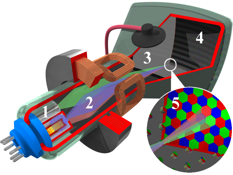
Die CRT hat drei Strahlenkanonen, die Pixel für Pixel, Zeile für Zeile abfahren. (und brauchen dann einige Zeit, um zum Ausgangspunkt zurückzukehren). Der Bildschirm verfügt über bunte Leuchtstoffe, die noch eine Weile weiter leuchten, nachdem der Strahl sie durchquert hat. Beim nächsten Durchgang der Strahlenkanone über dieses bestimmte Pixel könnte sich die Intensität des Strahls geändert haben, was wir als dunkleres Pixel sehen werden. Unser Gehirn verschmilzt die benachbarten farbigen Leuchtstoffpixel zu einem Pixel und ist nicht in der Lage, die Helligkeitsänderungen zwischen den Strahlengängen zu erkennen.
Auf diese Weise wird die Illusion eines bewegten Bildes erzeugt.
In der Tat müssen nicht alle Daten am Anfang des Bildes vorhanden sein - aber nur den aktuellen Helligkeitswert der Pixel. Die Intensität des Strahls wird dementsprechend verändert. Wir können dafür ein analoges Signal verwenden - zum Beispiel wird die Helligkeit erhöht, wenn wir die Spannung erhöhen.
Wir brauchen drei verschiedene Drähte für die verschiedenen Farben (um jede Strahlenkanone einzeln anzusteuern), und wir brauchen eine Möglichkeit, dem Monitor mitzuteilen, wann eine neue Zeile gestartet werden muss und wann ein neues Bild gestartet werden muss (wenn alle Zeilen angezeigt worden sind).
VGA (Video-Grafik-Array)
VGA wurde mit Blick auf diese Röhrenmonitore entwickelt. Es ist immer noch relativ häufig als Eingang bei Monitoren zu finden, obwohl es mit der Umstellung auf eine vollständig digitale Übertragung zunehmend veraltet ist (dazu später mehr).
Dies ist auch der einfachste Standard für die Videoausgabe, der auf dem Pico funktioniert.
Neben einer Spezifikation (mit Standardauflösungsmodi) wurde auch ein Anschluss, der VGA-Anschluss, angegeben:
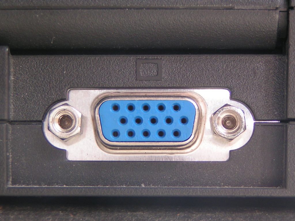
Er hat 15 Stifte:
- RED (rotes Video)
- GREEN (grünes Video)
- BLUE (blaues Video)
- ID2/RES (reserviert)
- GND (Masse HSync)
- RED_RTN (rote Rückleitung, analoge Masse für Rot)
- GREEN_RTN (Grüner Rücklauf, analoge Masse für Grün)
- BLUE_RTN (Blauer Rücklauf, analoge Masse für Blau)
- KEY/PWR (+5 V DC versorgt den EDID EEPROM-Chip bei einigen Monitoren)
- GND (Masse VSync, DDC)
- ID0/RES (reserviert)
- ID1/SDA (I2C-Daten seit DDC2)
- HSync (Horizontale Synchronisation)
- VSync (Vertikale Synchronisation)
- ID3/SCL (I2C-Takt seit DDC2)
Hinweis: VGA-Kabel können unterschiedliche Auflösungen, Farbtiefen und Bildwiederholfrequenzen unterstützen, wobei das Wort "VGA" in Bezug auf die Auflösung normalerweise 640 x 480 bedeutet.
Wie Sie sehen, gibt es drei Drähte zur Übertragung der Bilddaten, einer für jede Farbe. Das Signal wird mit einer Spitzenspannung (maximal) von 0,7 V übertragen. Die für die Farben übertragenen Signale sind analoger Natur - höhere Spannungen erhöhen die Helligkeit, eine Spannung von 0 bedeutet, dass das Pixel dunkel/aus ist.
VGA-Ausgang auf dem Pico zum Laufen bringen
Das bedeutet, dass der Pico mit seinem 3,3-V-Digitalausgang genügend hohe Spannungen hat, um diese RGB-Pins in das VGA-Kabel zu treiben (das Spannungen von 0 bis 0,7 V erwartet). Wir müssen die Spannung mit Hilfe von Widerständen reduzieren.
Wir können einen einfachen DAC (Digital-Analog-Wandler) bauen, indem wir mehrere Widerstände und GPIO-Pins kombinieren. Je nach der Kombination der GPIO-Pins, die zu einem bestimmten Zeitpunkt aktiv sind, haben wir unterschiedliche Spannungspegel (= Helligkeitsstufen):
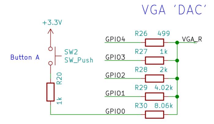
Wie Sie in der Abbildung oben sehen können, steuern fünf GPIOs (0 - 4) einen Kanal (in diesem Fall rot), was uns eine Tiefe von fünf Bit gibt. Die Widerstände sind 1:2:4:8:16 gewichtet, zum Beispiel hat das niederwertigste Bit (LSB) von Rot einen Widerstand von 8,06K.
Wenn Sie versuchen, diese Schaltung zu bauen, sollten Sie sich für 1 % Toleranzwiderstände um ein gutes Bild zu bekommen.
Siehe "Hardwareentwicklung mit dem RP2040", um zu verstehen, wie die Widerstandswerte berechnet wurden. Kurz gesagt, wenn wir alle auf einmal ansteuern, erhalten wir eine Spannung von 0,74 V, was für unsere Zwecke in Ordnung ist.
Genauer gesagt, schlägt dieses Referenzdesign vor, ein allgemein verwendetes 16-Bit-RGB-Datenformat (RGB-565) zu unterstützen, das 5 Bits für Rot und Blau und 6 für Grün verwendet. Wir können die tatsächliche physische Ausgabe für Grün auf 5 GPIO-Pins wie für die anderen Farben reduzieren, um einen Pin zu sparen.
Zusätzlich werden 2 weitere Pins für das horizontale und vertikale Blanking-Timing benötigt (HSYNC und VSYNC)
Damit haben wir insgesamt 17 GPIO-Pins zur Ansteuerung eines VGA-Ausgangs. Glücklicherweise hat der Pico 26 verfügbare GPIO-Pins, die es uns ermöglichen, den VGA-Ausgang zu steuern.
Wie bereits erwähnt, kann der Pico diese Pins dank der PIO-Funktion (programmierbare I/O) des RP2040 auch mit den erforderlichen Frequenzen und einem präzisen Timing ansteuern.
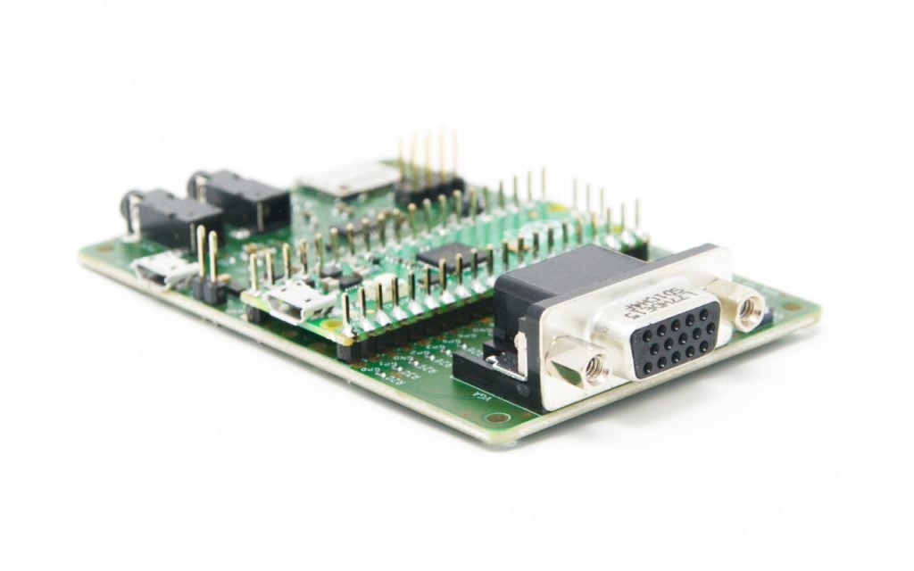
Raspberry Pi Pico VGA Video-Ausgangshardware
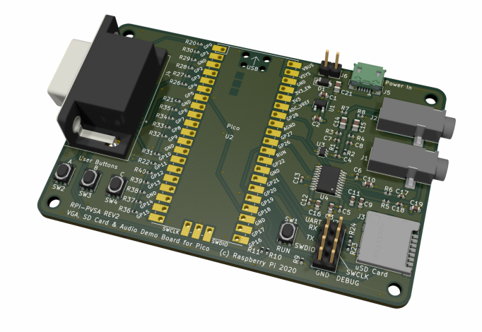
Raspberry Pi hat eine Trägerplatine für den Pico entwickelt und veröffentlicht, auf der verschiedene Funktionen zu sehen sind:
- VGA-Ausgang
- Tasten
- microSD-Steckplatz
- Audioausgänge (analog PWM, digital I2S)
Pico VGA / Audio / microSD-Karte kaufen
Wir (buyzero.de) sind derzeit dabei, dieses Referenzdesign-Board für uns zu bauen und zu montieren. Setzen Sie sich mit uns in Verbindung, wenn Sie benachrichtigt werden möchten, sobald das Board erworben werden kann.!
Die Pico VGA Board ist jetzt bei uns erhältlich, begrenzter Anfangsbestand!
In der Zwischenzeit hat Pimoroni auch eine Version dieses Boards erstellt, sie nennen es das Pimoroni Pico VGA Demo-Basis.
Nebenbei bemerkt: Jeder der 15 RGB-Ausgangspins muss immer noch mit etwa 17,58 Mbit/s angesteuert werden, was immer noch eine beeindruckende, aber viel handlichere Zahl ist!
Für die Ansteuerung des VGA-Ausgangs erforderliche Software
Da wir mit dem Pico arbeiten, gibt es keine "Grafiktreiber", die wir einfach installieren können. Wir müssen den Code selbst schreiben... oder auch nicht 🙂 .
Glücklicherweise haben die Leute, die das Hardware-Board für uns entworfen haben, bereits einen Code bereitgestellt, den wir verwenden können, so dass wir uns auf unser Projekt konzentrieren können.
Beispielcode, den Sie verwenden können, finden Sie im pico-playground Repository:
In diesem Repository befindet sich ein einfacher Movie Player namens Popcorn (der Filme in einem benutzerdefinierten Format abspielt). A big buck bunny, 1,6 GB groß, kann hier heruntergeladen werden. Beachten Sie, dass es sich hierbei um Rohdaten handelt, die auf eine SD-Karte geschrieben werden müssen - dieses Beispiel geht davon aus, dass Sie das VGA-Demoboard besitzen, das über einen SD-Steckplatz verfügt. Anweisungen für Filme konvertieren sind ebenfalls gegeben.
Der Code verwendet die pico_scanvideo Bibliothek (pico/scanvideo.h) aus der Datei pico_extras Repository. Werfen Sie auch einen Blick auf dieses Repository für Audio-Beispielcode!
- pico_scanvideo - enthält eine umfangreiche Dokumentation!
Die API gibt parallele RGB-Daten und Sync-Signale an Pins für DPI-VGA aus (unter Verwendung von Widerstands-DACs, wie oben beschrieben).
Ein klarer Punkt:
- Das Standard-PIO-Scanline-Programm akzeptiert lauflängenkodierte Daten - das bedeutet, dass Sie RAM sparen können, um flache Farbbereiche zu erzeugen (ich denke hier an Spiele!)
Im Allgemeinen sollten Sie die pico_scanvideo-Bibliothek anstatt den VGA-Ausgabecode von Grund auf neu zu entwickeln 🙂
gute Kodierungspraxis
Mehr Demos
Überprüfen Sie die scanvideo Verzeichnis des pico-playground Repository:
- MandelbrotEin Mandelbrot-Generator, der einen 320x240x16-Framebuffer verwendet
- sprite_demo: hüpfende Ebenköpfe (Video oben auf unserer Seite!)
- test_muster: Farbbalken anzeigen
Verwendung der VGA-Karte
Sie müssen CMake beim Kompilieren einen zusätzlichen Parameter übergeben:
-DPICO_BOARD=vgaboardTBD: Schritt-für-Schritt-Anleitungen hinzufügen
DVI: Digitale visuelle Schnittstelle
Die Technik schreitet voran. Das Leben entwickelt sich weiter. Röhrenbildschirme wurden mehr und mehr obsolet und durch modernere Flachbildschirme mit digitalen Schnittstellen ersetzt. Keine beweglichen Balken, nur Pixel.
Eine Zeit lang waren die Signale weiterhin analog - aber das ist nicht sehr wünschenswert, denn wir müssen etwas Digitales nehmen, es in etwas Analoges umwandeln und es dann wieder in etwas Digitales zurückwandeln. Das Bild wird weniger präzise, und wir haben zusätzliche Schaltungen, auf die wir verzichten könnten.
Dann kam DVI. Es bot die Möglichkeit, auch analoge Signale zu übertragen, so dass einfache DVI-zu-VGA-Adapter/Kabel gebaut werden konnten. Natürlich musste die Grafikkarte sowohl analoge als auch digitale Daten ausgeben. Dies trug jedoch dazu bei, dass der Standard akzeptiert wurde und sich durchsetzte.
Wir sind hier an den digitalen Signalen interessiert (DVI-D), da wir sie vom Raspberry Pi Pico aus bit-bangen möchten.
Bei DVI-D werden die Bilddaten auf seriellem Weg übertragen.
Eine "Single-Link"-DVI-Verbindung (die einfachste) besteht aus vier so genannte TMDS-Verbindungen (transition minimized differential signaling):
- rot
- grün
- blau
- Pixeluhr
Differentialsignalisierung wird verwendet, um Interferenzen zu minimieren (da
Wir haben insgesamt 24 Bits pro Pixel (8 Bits x 3 Farben) und kodieren die Daten mit einer 8b10b-Kodierung (8 Bits werden auf 10-Bit-Symbole auf der tatsächlichen physischen Zeile abgebildet, um u. a. einen Gleichstromausgleich zu erreichen).
DVI behandelt die Pixel ähnlich wie VGA: Jedes Mal, wenn das Bild wieder "anläuft", wird alles neu übertragen, und die Daten sind genau getaktet. Das ist wie bei einer Telefonleitung, die ständig in Betrieb ist, wenn zwei Personen miteinander sprechen.
Anmerkung: im Gegensatz dazu, DisplayPort behandelt die Daten als Pakete - was eine Reihe von Vorteilen hat.
Im Gegensatz zum oben beschriebenen VGA-Beispiel bedeutet dies, da die Daten digital und nicht als analoge Helligkeitswerte gesendet werden, ein wesentlich höheres Datenvolumen.
Lukas Zaunkönigein Ingenieur des Raspberry Pi, war der Meinung, dass der RP2040 (das Herzstück des Pico) auch in der Lage sein würde, einen DVI-Ausgang zu betreiben, wiederum unter Verwendung von PIO.
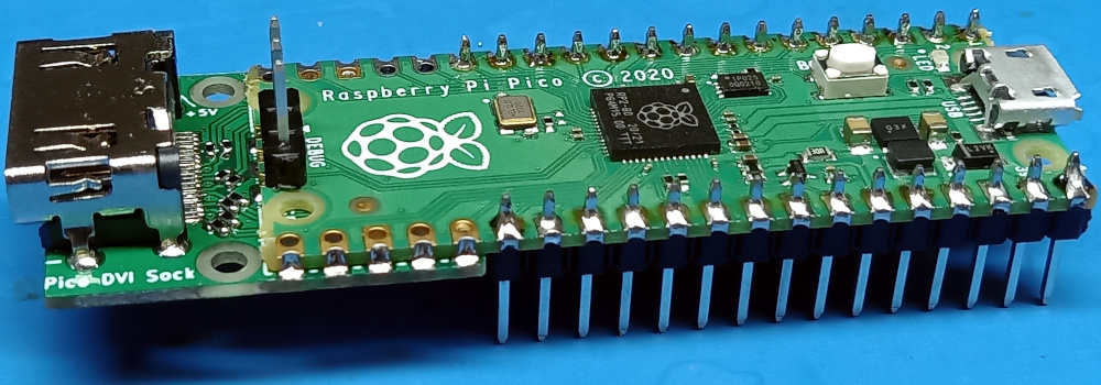
Das Ergebnis ist die PicoDVI-Repository & Projekte, und die Pico DVI Socke.
Luke Wren berechnete, dass etwa 252 Mbps serielle Daten muss über die GPIO-Digitalpads angesteuert werden - differentiell seriell, was mit zwei Single-Ended-Pads emuliert wird.
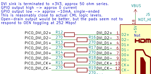
Oben sehen Sie die Schaltung, die zur Ansteuerung des DVI-Ausgangs verwendet wird (unter Verwendung eines HDMI-Anschlusses, mehr dazu weiter unten) - sind einfach mehrere 270 Ohm Widerstände.
Luke Wren ging sogar noch weiter und fügte seinem PicoDVI-Layout über eine Steckkarte einen doppelten DVI-Ausgang hinzu:
HDMI: abwärtskompatibel mit DVI
HDMI ist die nächste Generation von Anschlüssen (und steht in Konkurrenz zu DisplayPort). Es ist vollständig abwärtskompatibel mit den digitalen DVI-Signalen - daher können Sie einfache, rein passive DVI/HDMI-Konverter verwenden.
Pico DVI Socke
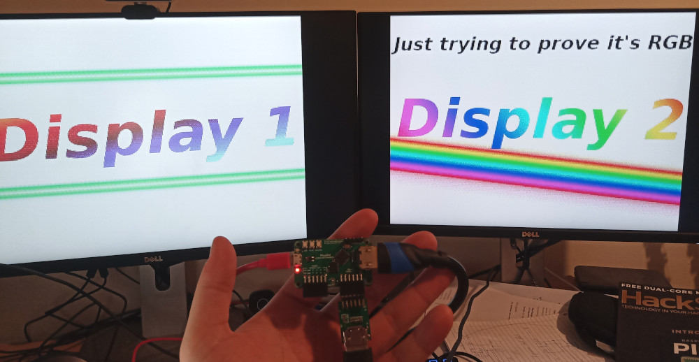
Der Pico DVI Sock ist eine einfache und kostengünstige Lösung, um einen digitalen Videoausgang zu Ihrem Pi hinzuzufügen. Er wurde von Luke Wren entwickelt (siehe Beschreibung oben). Es handelt sich um einen DVI-Ausgang mit einem HDMI-Anschluss. Da HDMI abwärtskompatibel zu DVI ist, können Sie ein HDMI-Kabel verwenden, um Ihren Pico an HDMI-Bildschirme anzuschließen:
Programmierung der Pico DVI-Socke
TL;DR
Sie können unsere picodvi-test.zip und fangen Sie an, mit den .UF2-Beispielkompilierungen darin herumzuspielen. Es enthält auch eine PDF-Datei, die Ihnen eine Schritt-für-Schritt-Anleitung bietet.
Code-Beispiele
Luke Wren bietet Code-Beispiele in seinem Repository. Um sie jedoch mit dem Pico DVI Sock zu verwenden, müssen Sie die richtige Konfiguration einstellen. Wir zeigen Ihnen in diesem Mini-Tutorial, wie das geht.
Installationsvoraussetzungen
sudo apt install cmake gcc-arm-none-eabi libnewlib-arm-none-eabi build-essentialKlonen Sie das PicoDVI-Repositorium von Luke Wren:
cd ~
mkdir pico
cd pico
git clone https://github.com/raspberrypi/pico-sdk
cd pico-sdk
git submodule update --init
cd ~/pico
git clone https://github.com/Wren6991/PicoDVI.git
Um die Code-Beispiele mit dem Pico DVI Sock zu verwenden, müssen Sie die Option korrekte Pin-Konfiguration zu verwenden. Fügen Sie die folgende Zeile hinzu common_dvi_pin_configs.h nur vor die erste #ifndef
#define DEFAULT_DVI_SERIAL_CONFIG pico_sock_cfg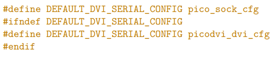
Erstellung der Beispiele
cd PicoDVI/software/
mkdir build
cd build
export PICO_SDK_PATH=~/pico/pico-sdk
make -j$(nproc)
Installieren Sie die Beispiele auf dem Pico
Die erstellten Beispiele befinden sich im Ordner software/build/apps.
Halten Sie die BOOTSEL-Taste auf dem Pico gedrückt und schließen Sie das Board dann über den microUSB-Anschluss an Ihren PC an. Kopieren Sie die entsprechende .uf2-Datei, die Sie ausprobieren möchten - z. B. sprite_bounce.uf2 - und fügen Sie sie auf dem Pico ein.
Der Pico wird automatisch neu gestartet, und Sie sollten in der Lage sein, die Ausgabe am HDMI-Anschluss zu sehen (denken Sie daran, dass es eigentlich DVI ist :-)).
Herunterladen
Sie können unsere picodvi-test.zip und fangen Sie an, mit den .UF2-Beispielkompilierungen darin herumzuspielen. Es enthält auch eine PDF-Datei, die Ihnen eine Schritt-für-Schritt-Anleitung bietet. Wenn die sprite_bounce.uf2 Beispiel bei Ihnen nicht funktioniert, versuchen Sie es mit einem anderen Monitor - möglicherweise sind nicht alle Monitore mit diesem Videoausgang kompatibel.
Wenn Sie so weit gekommen sind, lassen Sie uns in den Kommentaren wissen, wie es für Sie funktioniert hat und welche Projektideen Ihnen eingefallen sind!
Pico DVI-Socke kaufen
Unsere Schwesterseite, buyzero.de, führt die Pico DVI Socke in zwei Varianten:
- Nur Pico DVI-Buchse (zum Selbstlöten) @ 6,58 € derzeit
- Pico DVI Sock auf Pico, mit vorgelöteten Headern @ 17,89 € derzeit
Sidenote: DBI & DSI-Anzeigen
Nebenbei bemerkt, das Raspberry Pi Pico Extras Repository hat Platzhalter für DBI (16 Bit MIPI DBI Displays - mit paralleler Datenübermittlung) und DSI (MIPI serielle Displays), so dass wir in Zukunft vielleicht auch Unterstützung für diese Displays sehen werden.
Gibt es ein Beispiel für einen Composite-Ausgang mit Genlock?
Ich denke, dass eine Composite-Ausgabe möglich sein sollte, habe aber noch nichts in der freien Natur darüber gesehen.
Als Alternative zu scanvideo habe ich eine andere VGA/TV-Bibliothek für Raspberry Pico implementiert - 'PicoVGA', die meiner Meinung nach einfacher zu benutzen ist: http://www.breatharian.eu/hw/picovga/index_en.html
Vielen Dank für die Informationen über Ihre Bibliothek!
Hey, kann dieses HDMI als INPUT verwendet werden und die Daten verarbeiten.
so wie es programmiert ist, und da die Widerstände das Ausgangssignal des Raspberry Pi begrenzen - nein.
möglicherweise könnte man eine Anpassung des Designs verwenden, mit etwas, das den Signalpegel erhöht, anstatt ihn zu senken / und natürlich angepassten Code für die Ausgänge, damit sie als Eingänge funktionieren, um die Videodaten im Pico verarbeiten zu können.
Dennoch ein paar praktische Tipps. Dank der Silizium-Lotterie kann es vorkommen, dass Ihr spezielles Gerät die GPU und den CPU-Teil nicht proportional übertaktet. Wenn Sie also keine schnellere Grafik benötigen, sollten Sie die GPU nicht übertakten. Dies erhöht die Chance, dass Sie höher übertakten und ein stabiles System haben. Auch ein geringerer Stromverbrauch und eine geringere Stromzufuhr bedeuten mehr Stabilität. Raspberry Pis mit 4 CPU-Kernen können bei Belastung mit allen 4 Kernen an eine Stromversorgungsgrenze stoßen. Der integrierte PMIC (Power Management IC) liefert möglicherweise nicht den benötigten Strom für alle Kerne und schaltet sich für kurze Zeit ab, wodurch der Pi neu gestartet wird. Kühlen Sie auch den PMIC. Die maximale Spannung sollte nicht überschritten werden, wenn alle Kerne belastet werden sollen (Kernel-Compilierung, schweres Number-Crunching usw.). Hier haben wir einen RPI4, der bei 1850MHz mit allen Kernen aktiv mit over_voltage=2 laufen kann, aber mit höherer over_voltage=3 rebootet er, wenn er belastet wird. Eine höhere Überspannung bedeutet auch einen höheren Strom, und die PMIC-Schaltung hat einen begrenzten Ausgangsstrom. Je heißer der PMIC und die ihn umgebenden Induktivitäten sind, desto weniger Strom kann er liefern. Dies ist eine Einschränkung des PMIC-Chips, nicht des BCM-Chipsatzes. Wenn Sie also gelegentliche Neustarts unter hoher Last erleben, kann das an der Überhitzung des PMIC liegen. Wenn Ihr Pi sich aufhängt, liegt es nicht an diesem speziellen Problem, sondern vielleicht am Verlust der Silizium-Lotterie. Die Untertaktung eines GPU-Teils kann ein interessanter Weg sein, um die Übertaktbarkeit zu erhöhen (stabileres System), aber AFAIK hatten ältere Raspberry Pis einen an die GPU gebundenen L2-Cache, so dass die Untertaktung auch die CPU verlangsamen kann. Ich habe dokumentiert, wie sich der PMIC des Raspberry Pi 4 erwärmt - alle anderen Chips werden direkt über einen Kühlkörper gekühlt. Die Ansicht ist von der Unterseite, d.h. man sieht die beheizte Platine. Die untere linke Ecke ist der PMIC.
Herzlichen Dank für diese praktischen Tipps!
Hallo,
Ich bin ein Noob hier. Kann jemand einen Schaltplan für eine cvbs-Display-Ausgabe zur Verfügung stellen. Und jede notwendige Änderung am Quellcode?
Sorry, keine Ahnung für die cvbs
Hallo
Danke für den schönen Beitrag. Ich habe ihn von Anfang bis fast zum Ende gelesen 😉 .
Ich habe jedoch einige unangenehme Fragen:
1. Der RPi Pico hat PWM. Ist es möglich, einen einzigen Pin mit PWM zu verwenden, um ein analoges Signal an die VGA-Pins zu senden? Auch einfachere und kleine Schaltungen.
2. Ist es möglich, wieder einen analogen AV-Ausgang vom RPi Pico zu bekommen, vielleicht mit PWM? Ich denke, die meisten TVs unterstützen das. Vielleicht unter Verwendung eines Moduls wie https://thecaferobot.com/store/pub/media/catalog/product/cache/14d1897c7f1bd4f35a7de1523300314a/l/c/lcd-01-057-1.jpg erhältlich in einem lokalen Geschäft, zu dem ich Zugang habe. Allerdings ist das Bild, das ich geschickt habe, ein Modul für Arduino, aber es sollte möglich sein, mit Pico als auch zu verwenden, nehme ich an.
3. Wenn man mit VGA oder DVI in Kombination mit Pico gehen wollte, ist es möglich, nicht diese Helfer VGA oder DVI-Boards verwenden? Weil diese nicht in meiner Region verfügbar sind, um eine zu kaufen und meine Fähigkeiten sind nicht gut genug, um eine selbst zu erstellen.
1. PWM-Pins haben wahrscheinlich nicht die Timing-Präzision, die Sie für die Videoausgabe haben möchten (deshalb verwenden wir PIO, das ein sehr präzises Timing hat). Aber warum es nicht versuchen 🙂
2. Ich nehme an, dass es möglich sein sollte, einen analogen AV-Ausgang aus dem Raspberry Pi Pico zu erzeugen. Ich bezweifle, dass die PWM wird "genug" für diese (wäre glücklich zu hören, jemand mit mehr Erfahrung chime in auf sie!)
Beachten Sie, dass PWM das Signal einfach nur ein- und ausschaltet, während die z. B. auf der VGA-Platine verwendete Widerstandsleiter kontinuierliche Signalpegel liefert. Damit die PWM-Lösung funktioniert, muss sie also mit viel höheren Frequenzen arbeiten als für das eigentliche Signal erforderlich ist. Ich bin mir auch nicht sicher, wie externe Hardware auf ein PWM-Signal anstelle eines kontinuierlichen Analogsignals reagieren würde.
Möglicherweise könnte man sie mit einem sehr kleinen Kondensator glätten, wofür man entsprechende Berechnungen anstellen müsste.
3. die VGA-/DVI-Hilfsplatinen enthalten alles Notwendige (hauptsächlich Widerstände). Sie können auf den Schaltplan schauen und bauen Sie Ihre eigenen Setup auf einem Breadboard möglicherweise, ich habe gesehen, jemand tun es für VGA.
Allerdings versenden wir auch international:
https://buyzero.de/products/raspberry-pi-pico-vga-audio-sd-expansion-board?variant=39412666335412
Pico DVI Socke @ buyzero.de Shop
Tolle Infos. Danke!
Ich habe auch dies gefunden: Composite-Video-Ausgang am Raspberry Pico
http://www.breakintoprogram.co.uk/projects/pico/composite-video-on-the-raspberry-pi-pico
Ich habe es geschafft, den picoDVI von Wren6991 zu bauen und ihn mit einem dreifachen ADC zu integrieren, um RGB 15Khz (640×240) abzutasten.
Bei 320×240, wo nur ein Kern verwendet wird, wird der andere in Ruhe gelassen, um HSYNC/VSYNC-Interrupts zu empfangen und DMA-Übertragungen ohne Probleme vorzubereiten, aber bei 640×480 blockiert die Verwendung von 2 Kernen das System, um richtig zu arbeiten.
Da ich die Hälfte der Linien benötige, gibt es eine Möglichkeit, eine immer vorbereitete schwarze Linie für ungerade Linien zu haben? damit gebe ich einen Kern für meine Dutties frei.
Ich glaube nicht, dass Sie irgendwelche Leerzeilen senden müssen. Sie senden alle ungeraden Zeilen, senden ein Vsync-Signal mit einer zusätzlichen halben Zeile und senden die geraden Zeilen. Recherchieren Sie etwas über "interlaced video sync pulses".
Weiß jemand, wie man selbst gedrehte Videos laden kann und nicht nur die Beispielvideos? Vielen Dank im Voraus!
Ich bin daran interessiert, es für eine einzigartige audiovisuelle Anzeige zu verwenden. Bitte, kann mir jemand sagen:
Können Sie den Pico über das HDMI-Kabel mit Strom versorgen, auch wenn er sich auf der Zeitübertragungsseite des Kabels befindet?
Können Sie den Rec2100-Farbraum (Rec 2020 HDR-Farbraum) verwenden?
Ist es möglich, zusätzliche Leitungen an den HDMI-Anschluss anzuschließen, um Audio (und rec2020/HDR-Signalisierung) zu übertragen?
Können Sie Video über eines der USB-Videoformate ausgeben (Video von einem unveränderten Pico über einen USB-zu-Pico-Adapter)?
Kann ich mit dem Pico Wireless Miracast nutzen?
Kann ein normaler Bitmap-Videomodus erstellt und für Spielgrafiken mit übrig gebliebenen Zyklen manipuliert werden?
Seedstudio bietet ein Mini RP2040 Board an. Kann das HDMI-Interface-Board und Software, auf, dass zu arbeiten. Sie haben auch eine RiscV-Version mit Wifi, so wäre es gut, wenn es für das neu kompilieren könnte.
https://www.seeedstudio.com/XIAO-RP2040-v1-0-p-5026.html?queryID=31d59a67f7c148df996ba9c1bb7563e3&objectID=5026&indexName=bazaar_retailer_products
Ich interessiere mich für Spieleanwendungen, wie z. B. die Verwendung einer Spieleuhr.
Gibt es eine minimale JavaScript-Laufzeitplattform, die dort eingesetzt werden kann?
Entschuldigung, dass ich so viel verlange, aber
Sehr interessant.
Ich danke Ihnen.
Kann ich Ihre Karte zusammen mit dem MMBasic-Interpreter von Geoff verwenden? Gibt es irgendwelche Hardware-Einschränkungen für meine Programme aufgrund Ihrer Karte?
Große Geister denken ähnlich, ich habe auch in diese Richtung gedacht! Ich habe bereits den Raspberry Pico-basierten MMBASIC-Computer mit VGA-Ausgang gebaut, und es ist nichts weniger als fantastisch! Der DVI-D-Ausgang (Pseudo-HDMI) hebt die Grafikfähigkeiten jedoch auf ein neues Niveau! Natürlich muss MMBASIC die höhere Farbtiefe oder Auflösung nicht voll ausnutzen, aber ein Betrieb bei 640×480 mit z.B. 64 Farben wäre schon ganz schön krass.
Damit sehe ich zwei unmittelbare Probleme voraus.
1. Die VGA-Lösung verwendet auch die PIO-Pins, und einer der Kerne wird für Sprite-Management, Frame-Buffering usw. verwendet. Ich glaube. Zumindest wird eine Codeänderung erforderlich sein, um die VGA-PIO-Implementierung zu ersetzen. Als API wäre ich auch überrascht, wenn die Schnittstelle zwischen PIO (VGA) und dem Framebuffer-Kerncode die gleiche ist wie die DVI-PIO-Lösung, aber vielleicht irre ich mich. Wie auch immer, es wird eine Code-Änderung geben müssen.
2. RAM. Es gibt nicht genug von dem Zeug, also werden höhere Auflösungen und höhere Farbtiefen ein Problem sein. Aber ich glaube, ich habe eine Lösung. Externes PSRAM verwenden, und vielleicht einen RP2040/Pico als "GPU" einsetzen, der sein eigenes PSRAM angeschlossen hat. Er spricht dann mit einem zweiten RP2040, der die "CPU" oder das Gehirn des Systems darstellt, auf dem MMBASIC läuft, und er kann grafische Elemente manipulieren/verschieben, indem er die GPU mit minimalem Overhead anweist (z.B. über I2C Link). Ich will/brauche das 😉 .
64 Euro für das "Raspberry Pi Pico VGA Audio SD Expansion Board"? Man würde besser eine Null verwenden...
Pimoroni hat eine weniger teuer (30 €), aber immer noch eine Menge. Die DVI-Socke kostet nur ein paar Euro ...