Control a servo with Raspberry Pi Pico W and PWM
A servo is one of the most fundamental ways to learn to use pulse width modulation (PWM) with the Raspberry Pi. In this article, I’m going to show you how to do this with a Raspberry Pi Pico W.
PWM tutorial objectives
- Learn how to use PWM to control the angle of the servo
- Set up a server with the Pico W
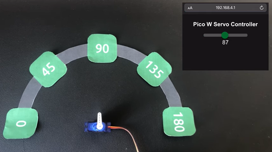
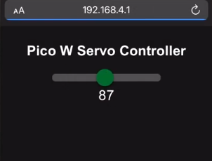
- Server delivers web page with a slider to control servo
Parts needed
- Raspberry Pi Pico W with headers
- Jumper wire
- Servo (we’re using the Tower Pro SG90 micro servo)
What is pulse width modulation?
Children find it amusing to switch lights on and off repeatedly.
To them, it’s just so amusing to see lights flicker on and off as they toggle the light switch. Parents might not find it amusing, but this provides a learning moment for all of us.
If you or your children have done that, then you have experienced a primitive form of pulse width modulation.
With a Raspberry Pi, you can easily do this in an automated fashion. In essence, you’d tell the Raspberry Pi how many times you’d want things to be “ON” in a specific period.
This allows you to dim LEDs:
As well, this allows you to control the angle of the servo’s arm.
An important PWM concept: the duty cycle
A duty cycle is basically the time the circuit stays “high”, which means it’s turned on.
So, let’s your circuit is on half the time. We can therefore say that the duty cycle is at 50%.
If you have it turned on all the time, its duty cycle would be at 100%, and vice versa, turned off all the time means a 0

Going back to the example of a child turning lights on and off at a regular rate, the reason why the lights don’t light up fully or dim fully is because we are only delivering a voltage output for a specific portion of time.
For an LED, this means the LED is lit for a period of time, then power is pulled, then power is delivered again, and repeat.
So, the LED never gets bright enough to reach its full brightness, neither does it have enough time to go completely dark.
SG90 servo control with PWM
We’d have to be cautious here as not all servos operate the same way. This tutorial is specific to the Tower Pro SG90 micro servo.
The SG90 has a 180-degree rotation, but some servos are 120-degree servos. Radio control hobby servos are most likely to be 120 degree servos, so make sure to check the datasheet of the servo you’d want to manipulate as it’s possible to damage servos if you give it an out-of-range signal.
This is the datasheet for the SG90, from Luxor Parts:
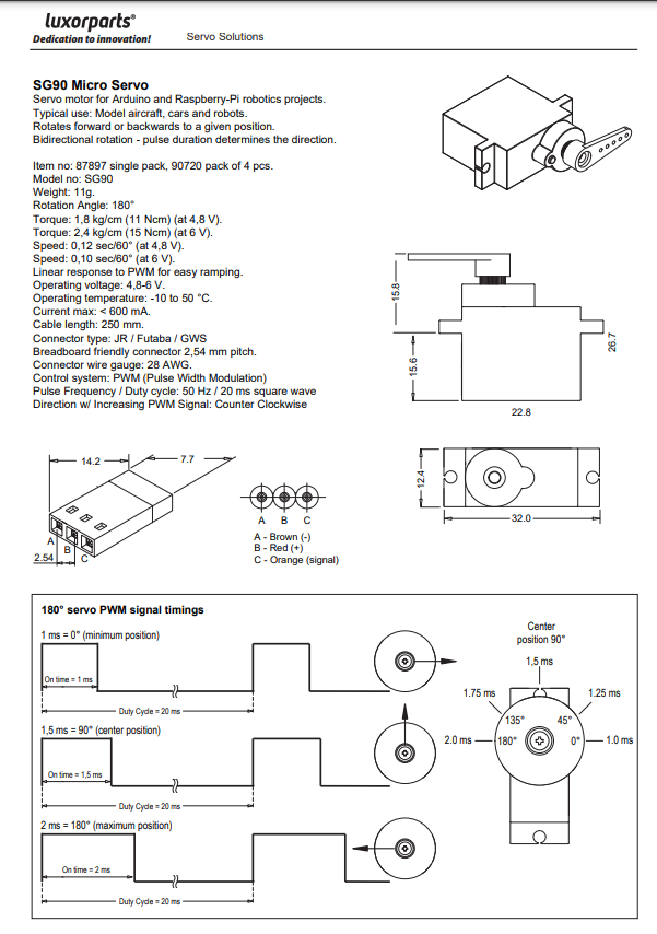
The datasheet tells you two important things: which colour corresponds to positive, ground and signal and the pulse frequency/duty cycle.
- Brown = negative
- Red = positive
- Orange = signal
And for pulse frequency/duty cycle
- You will need to have a duty cycle of 20ms or 50Hz.
- A signal of 1ms = zero degrees
- A signal of 2ms = 180 degrees rotated

This means that every ms, the servo will look for an update. If you continue sending it a 2ms signal, it will stay at full rotation (180 degrees). If you change it to 1.5ms, it will rotate 90 degrees, and at 1ms, it will be rotated zero degrees.

Connecting the servo to the Pico W
In order to use our code, you have to connect the signal wire to GPIO 0. The signal wire is the orange wire on the SG90.
Then, connect the red wire to VBUS (which gives you 5V). As you can see from the datasheet, the operating voltage for the SG50 is 4.8V to 6V, so the 3.3V pin on the Pico W won’t work.
Coding the Pico W servo control
You can find the code here on our GitHub.
Let’s go through the code.
In main.py, which is a naming convention for the file we want to run on boot, we create a class for the servo and instantiate it:
class Servo:
    def __init__(self, MIN_DUTY=300000, MAX_DUTY=2300000, pin=0, freq=50):
        self.pwm = machine.PWM(machine.Pin(pin))
        self.pwm.freq(freq)
        self.MIN_DUTY = MIN_DUTY
        self.MAX_DUTY = MAX_DUTY

    def rotateDeg(self, deg):
        if deg < 0:
            deg = 0
        elif deg > 180:
            deg = 180
        duty_ns = int(self.MAX_DUTY - deg * (self.MAX_DUTY-self.MIN_DUTY)/180)
        self.pwm.duty_ns(duty_ns)

servo = Servo()
The Servo class uses the machine.PWM class available in MicroPython. See documentation here.
In this example, we are using the Pico W as an access point. Here’s the code to make that happen:
ssid = 'Servo-Control'
password = 'PicoW-Servo'

ap = network.WLAN(network.AP_IF)
ap.config(essid=ssid, password=password)
ap.active(True)

while ap.active() == False:
  pass

print('Connection successful')
print(ap.ifconfig())
As you can see from the first two lines, the SSID you’re looking for is Servo-Control and the password is PicoW-Servo.
Once you have signed onto the WiFi network, you can go to the IP address of the Pico W, which by default is 192.168.4.1. Alternatively, you can also check the log on Thonny to see what your Pico’s IP address is.
How does the web page communicate with the servo?
When you log onto the Pico W’s IP address, you are sent the index.html file, which can be found on the Github repo.
The index.html file has these important lines:
 <form id="form">
            <input type="range" class="slider" min="0" max="180" value="slider_value" name="servo" id="servo">
            <output></output>
        </form>
As you can see, there’s an <input> object which is the slider.
There’s also an <output> which displays the degree of rotation.
The JavaScript portion updates the <output> as well as updates the URL so that the Pico W can capture the data and rotate the servo.
The <input> and <output> elements are have a <form> parent.
Here’s the script on the front end,