Raspberry Pi Pico Video Output
TL;DR
The Raspberry Pi Pico is an incredible little microcontroller. While it does not have a video output interface built-in, like it’s bigger Raspberry Pi Zero / 1 / 2 / 3 / 4 / 400 siblings (HDMI / double HDMI in their case), it is possible to add a video output to the Pico! (As VGA or DVI over an HDMI connector, read on for details)
In this post, we’ll explain why a video out is a very special feature for microcontrollers, and which types of video out you can build or purchase for your Pico. We’ll also show you some sample code – already precompiled for you, so you can download it directly, and then we’ll talk about what you need to modify to make it run.
Our sister shop, buyzero.de, sells a variety of Pico accessories – including the DVI Sock, and the VGA carrier board for the Pico.
Note: the Pico does not have a Linux operating system like the Raspberry Pi Zero W for example. So you’ll most likely have to dive a bit deeper into learning how to code & upload your applications to the Pico. If that’s not your thing, the Pi Zero W might be a better fit to start playing around 🙂
If you’ve succeeded in doing your own video project with the Raspberry Pi Pico, let us know in the comments!
Why is adding a Raspberry Pi Pico Video output a challenge?
The Raspberry Pi 400, for example, is based on the BCM2711 SoC. This system-on-a-chip has specialized hardware which takes care of the video output, perfectly preparing it in the format which is specified for the particular video interface(s), two HDMI ports in the case of the Pi 400. It also has a massive memory (of 4 GB), in which to store the video output data.
To understand this better we need to look at some fundamentals of computer video output:
Video display and transmission
We see the display on the screen “at once”. Our brain has massively parallel wiring, in which it ingests information from all available retina cells at once (cone cells and rod cells).

Photo by Karina Vorozheeva on Unsplash
(* the mechanism of transmission into the brain integrates information across several retina cells, but the fact remains that a lot of information is transmitted in parallel. Look into bipolar cells if you’re interested to know more)
The brain, however has latencies – it is not able to resolve changes in visual stimuli faster than 13 ms. (which is about 1 in 75 frames per second).
For us this means that if we want to display a really smooth animation, we need to show about 60 different static pictures per second. Our brain will interpret these static pictures as smooth and life-like playback.
Typically, we want these pictures to be in color.
We have three different photoreceptors for color, so the screen displays only these three different colors with different brightness. Again, our brain will synthesize the colors in between from this information it gets. (On a sidenote, purple does not really exist as it’s own wavelength – it’s a mixture of red and blue).
There are three primary colors:
- red
- green
- blue
Together, they are known as RGB. When you add all three of them, you get white. Adding red to green yields yellow, adding green to blue yields cyan, adding blue to red yields magenta.
So what we really want to output are:
- three different colors,
- each with a different brightness value
- ideally about 60 different values per second (60 Hz)
- a certain screen resolution – e.g. 640 x 480
Let’s calculate how much data this is per second:
- 3 colors
- x 8 bit color depth
- x 60
- x 640 x 480
= 442.368.000 bits per second = ca. 422 MBit/s
(Consider that for example the USB v1.1 interface on the Pico has about 10 Mbit/s – about 40 times less throughput!)
To output this information, ideally you would also want to hold this information as a bitmap in your RAM – one part of your application will update the image in the RAM, while another will take care of delivering the data in a format which a monitor can work with. This needs to be RAM, since we are operating at high speeds, and need to be able to read this reliably with small latencies – which Flash memory would not provide.
Let’s calculate how much RAM we need:
- 640 x 480 (resolution)
- x 3 (colors)
- x 8 bits (color depth)
= 7372800 bits = 900 kBytes (note 1 Byte = 8 Bits)
While 900 kBytes will fit many times over into the RAM of a Raspberry Pi 400, the Pico only has 264KB RAM.
As you see, we will need to reduce some of the parameters (e.g. resolution, color depth, …) if we want to fit a bitmap into the RAM, or we need to come up with some clever ideas of how to make it work without storing everything!
Pico’s RP2040 PIO allows to output video data
Finally, while the Raspberry Pi 400 and other Raspberry Pi models have dedicated hardware circuitry to process all this information and output it in a reliable manner, the Pico doesn’t have special circuits dedicated just for video output.
But it has one trick up its sleeve! The RP2040 supports PIO (programmable IO). The PIO is dedicated to emulating different interfaces with precise timing, and it is very very powerful! It can be programmed to read from the RAM and output at high speeds.
We will be using the PIO to output video to some GPIO pins, and will use some additional circuitry (resistors) to bring the signal into the desired condition, depending on the video output interface we want to connect the Pico to.
Video output format history
Before getting into the meat of how you can add a video output to your Raspberry Pi Pico, let’s have a look at a little history of video output formats.
As discussed already, the human eye is not capable of detecting changes in images faster than about 13 ms. One of the first approaches to build computer monitors was therefore the CRT (cathode ray tube) monitor.
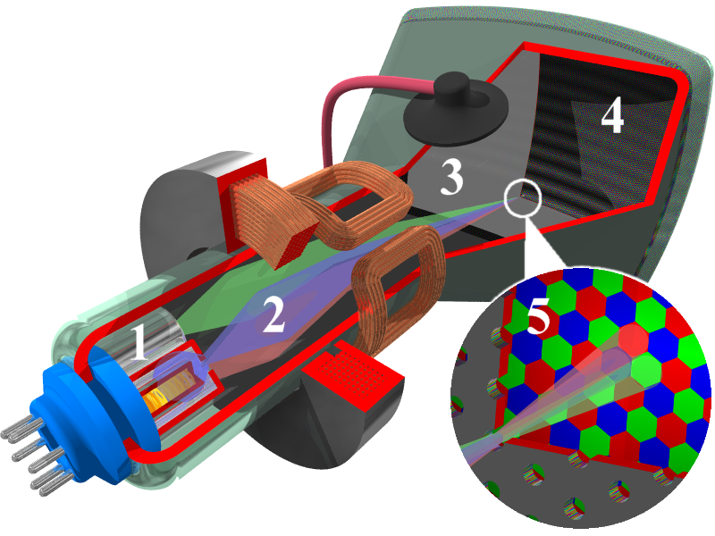
The CRT has three ray guns, which sweep pixel by pixel, line by line. (and then need some time to return to the starting point). The screen has colorful phosphors, which will continue to emit light for a while after the ray has passed through it. On the next sweep of the ray gun over this particular pixel the intensity of the ray might have changed, which we’ll see as a darker pixel. Our brain fuses the adjacent colorful phosphor pixels into one pixel, and is not able to notice the brightness changes between ray sweeps.
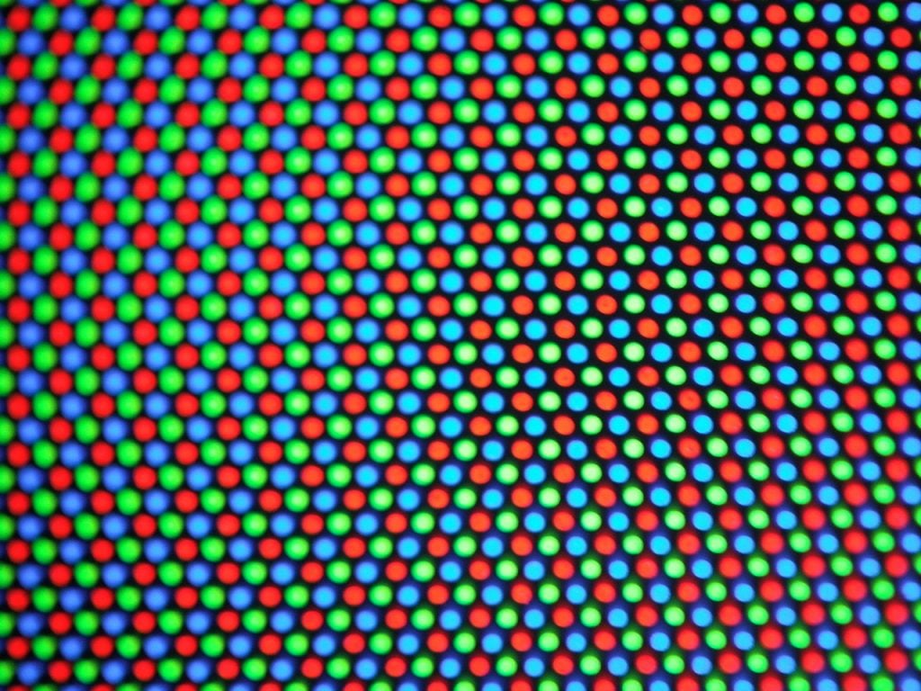
This way the illusion of a moving image is created.
In effect they don’t need to have all the data present at the start of the image – but just the current pixel brigthness value. The intesity of the ray will be modified according to this. We can use an analogue signal for this – for example, increasing the voltage will increase the brightness.
We need three different wires for the different colors (to drive each ray gun individually), and we need to have a way to let the monitor know when a new line needs to be started, and when a new image has to be started (when all lines have been shown).
VGA (video graphics array)
VGA was designed with these CRT monitors in mind. It is still reasonably common as an input on monitors, even though it’s becoming increasingly obsolete as we shift to completely digital transmission (more on that later).
This is also the easiest video output standard to get working on the Pico.
Next to a specification (with default resolution modes), it specified a connector, the VGA connector:
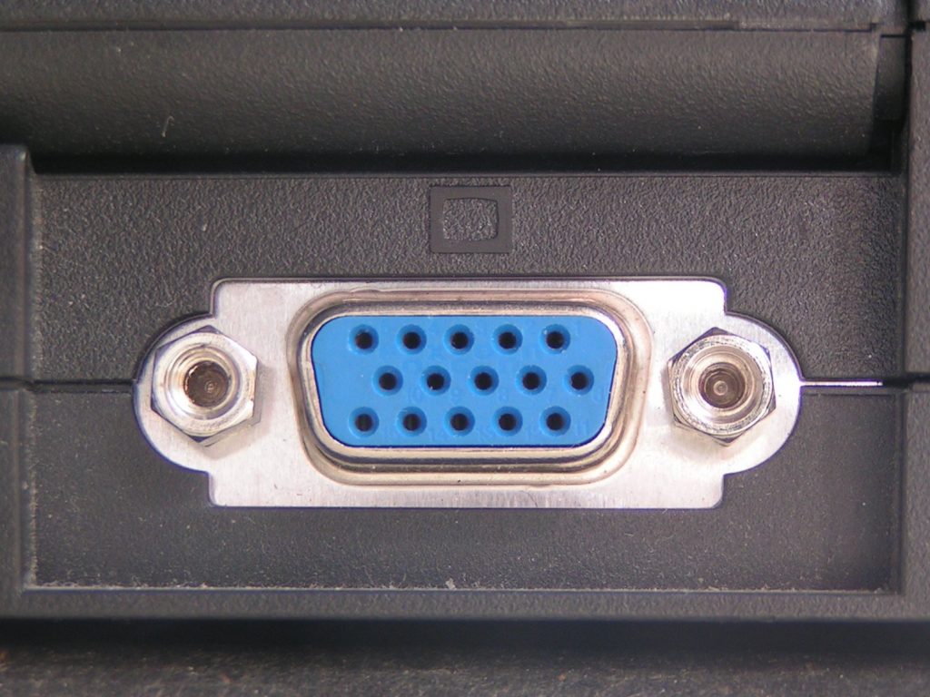
It has 15 pins:
- RED (red video)
- GREEN (green video)
- BLUE (blue video)
- ID2/RES (reserved)
- GND (Ground HSync)
- RED_RTN (red return, analog ground for red)
- GREEN_RTN (Green return, analog ground for green)
- BLUE_RTN (Blue return, analog ground for blue)
- KEY/PWR (+5 V DC powers EDID EEPROM chip on some monitors)
- GND (Ground VSync, DDC)
- ID0/RES (reserved)
- ID1/SDA (I2C data since DDC2)
- HSync (Horizontal Sync)
- VSync (Vertical Sync)
- ID3/SCL (I2C clock since DDC2)
Note: VGA cables can support different resolutions, color depths and refresh frequencies, whereas the word “VGA” when referring to the resolution usually means 640 x 480.
As you see, there are three wires carrying the image data, one for each color. The signal is transmitted with a peak (maximum) voltage of 0.7 V. The signals transmitted for the colors are analog in nature – higher voltages increase the brightness, a voltage of 0 means the pixel is dark / off.
Making VGA output work on the Pico
This means that the Pico, with it’s 3.3V digital output has high enough voltages to be able to drive these RGB pins into the VGA cable (which expects voltages of 0 – 0.7V). We actually need to reduce the voltage by using resistors.
We can build a simple DAC (digital analog converter) by combining several resistors and GPIO pins. Depending on the combination of GPIO pins which are active at any given moment, we have different voltage levels (= levels of brightness):

As you can see in the picture above, five GPIOs (0 -4) drive one channel (red in this case), which gives us a five-bit depth. The resistors are weighted 1:2:4:8:16, for example the least significant bit (LSB) of red has a 8.06K resistor.
When trying to build this circuit, you should go for 1 % tolerance resistors to get a good picture.
Please refer to “Hardware design with the RP2040” to understand how the resistor values were calculated. In short, if we drive all of them at once, we’ll have a voltage of 0.74 V which is OK for our purposes.
More specifically, what this reference design suggests is to support a commonly used 16-bit RGB data format (RGB-565), which uses 5 bits for red and blue, and 6 for green. We can reduce the actual physical output to the green to 5 GPIO pins as for the other colors, to save one pin.
In addition to that 2 more pins are needed for horizontal and vertical blanking timing (HSYNC and VSYNC)
This brings us to a total of 17 GPIO pins to drive a VGA output. Luckily, the Pico has 26 available GPIO pins, which allows us to drive the VGA output.
As mentioned previously, the Pico is also capable of driving these pins at the necessary frequencies and with precise timing, thanks to the RP2040 PIO feature (programmable I/O).
Raspberry Pi Pico VGA video output hardware

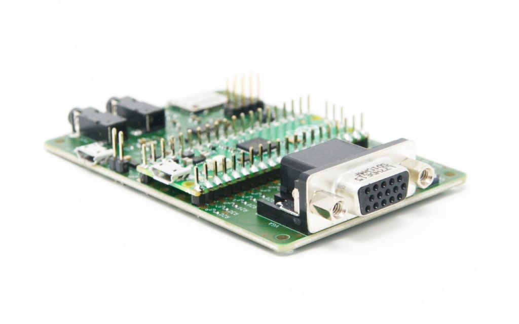
Raspberry Pi has designed and open-sourced a carrier board for the Pico which shows off different features:
- VGA output
- buttons
- microSD slot
- audio outputs (analog PWM, digital I2S)
Purchase the Pico VGA / Audio / microSD Board
We (buyzero.de) are currently in the process of having this reference design board built and assembled for us. Contact us if you want to be notified, once the board can be purchased!
The Pico VGA Board is now available for purchase from us, limited initial stock!
In the meantime, Pimoroni has also created a version of this board, they call it the Pimoroni Pico VGA Demo Base.
Side note: each pin of the 15 rgb output pins will still need to be driven at around 17.58 Mbit/s, which still is an impressive – but much more manageable number!
Software required to drive the VGA output
Since we’re working on the Pico, there are no “graphics drivers” we can simply install. We need to write the code ourselves… or not 🙂
Luckily, the people who designed the hardware board for us already supply some code we can use, so that we’re able to focus on our project.
Example code you can use can be found in the pico-playground Repository:
In this repository, there is a simple movie player called popcorn (which plays movies in a custom format). A big buck bunny, 1.6 GB in size can be downloaded here. Note that these are raw disk images to be written to an SD card – this example assumes you have the VGA demo board, which has an SD slot. Instructions for converting movies are also given.
The code uses the pico_scanvideo library (pico/scanvideo.h) from the pico_extras repository. Also have a look at that repository for audio sample code!
- pico_scanvideo – includes extensive documentation!
The API outputs parallel RGB data and sync signal on pins for DPI VGA (using resistor DACs, as described above).
A neat point:
- The default PIO scanline program accepts run-length-encoded data – this means that you can save RAM to generate flat color areas (I’m thinking games here!)
In general you would want to use the pico_scanvideo library instead of developing VGA output code from scratch 🙂
good coding practice
More demos
Check out the scanvideo directory of the pico-playground repository:
- mandelbrot: a mandelbrot generator using a 320x240x16 framebuffer
- sprite_demo: bouncing Eben heads (video at the top of our page!)
- test_pattern: Display color bars
Using the VGA Board
You need to pass an additional parameter to CMake while compiling:
-DPICO_BOARD=vgaboardTBD: Add step-by-step guides
DVI: Digital Visual Interface
Technology moves on. Life moves on. CRTs became more and more obsolete, superseded by more modern flat screens, which have digital interfaces. No moving beams, just pixels.
For a while, signals continued to be analog – but this is not very desirable, since we have to take something digital, transform it into something analog, and then transform it back into something digital again. The image will be less precise, and we have additional circuitry which we could dispense with.
Enter DVI. It cleverly offered an option to transmit analog signals as well, so simple DVI to VGA adapters / cables could be built. Of course, the graphics card would need to output both analog and digital data. But this helped to have the standard accepted and for it to become widespread.
We’re interested in the digital signals here (DVI-D), as we would like to bit-bang them from the Raspberry Pi Pico.
With DVI-D, the image data is transmitted in a serial way.
A “single link” (most basic) DVI connection consists of four so-called TMDS links (transition minimized differential signaling):
- red
- green
- blue
- pixel clock
Differential signalling is used to minimize interference (since
We have a total of 24 bits per pixel (8 bits x 3 colors), and encode the data using 8b10b encoding (8 bits are mapped to 10 bit symbols on the actual physical line to achieve DC balance amongst other things).
DVI treats the pixels similarly to VGA: everything is re-transmitted every time the image “starts” again, and the data is clocked precisely. This is like a telephone line, where the line is constantly in use when two people talk.
Note: in contrast to this, DisplayPort treats the data as packets – which has a number of advantages.
In contrast to the VGA example discussed above, since the data is sent digitally, instead of analog brightness values, this means much higher data volumes.
Luke Wren, an engineer with Raspberry Pi, believed that the RP2040 (at the heart of the Pico) would also be capable of driving DVI output, again using PIO.
The result is the PicoDVI repository & projects, and the Pico DVI Sock.
Luke Wren calculated that about 252 Mbps serial data has to be driven through the GPIO digital pads – differential serial, which is emulated with two single-ended pads.
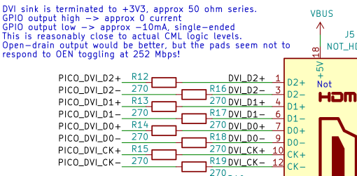
Above you see the circuit used to drive the DVI output (using an HDMI connector, more on this below) – are simply several 270 Ohm resistors.
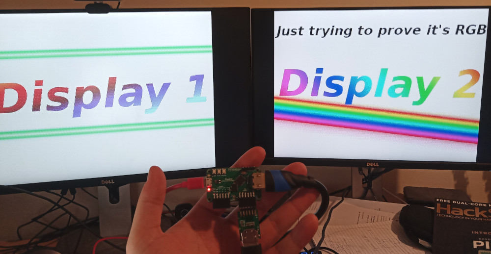
Luke Wren has even gone further and added dual DVI output to his PicoDVI layout by a plugin board:
HDMI: downwards compatible with DVI
HDMI is the next evolution of connectors (and in competition with DisplayPort). It is fully downwards compatible with the digital DVI signals – thus you can have simple, purely passive DVI / HDMI converters.
Pico DVI Sock
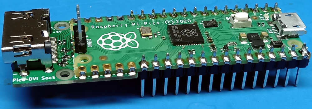
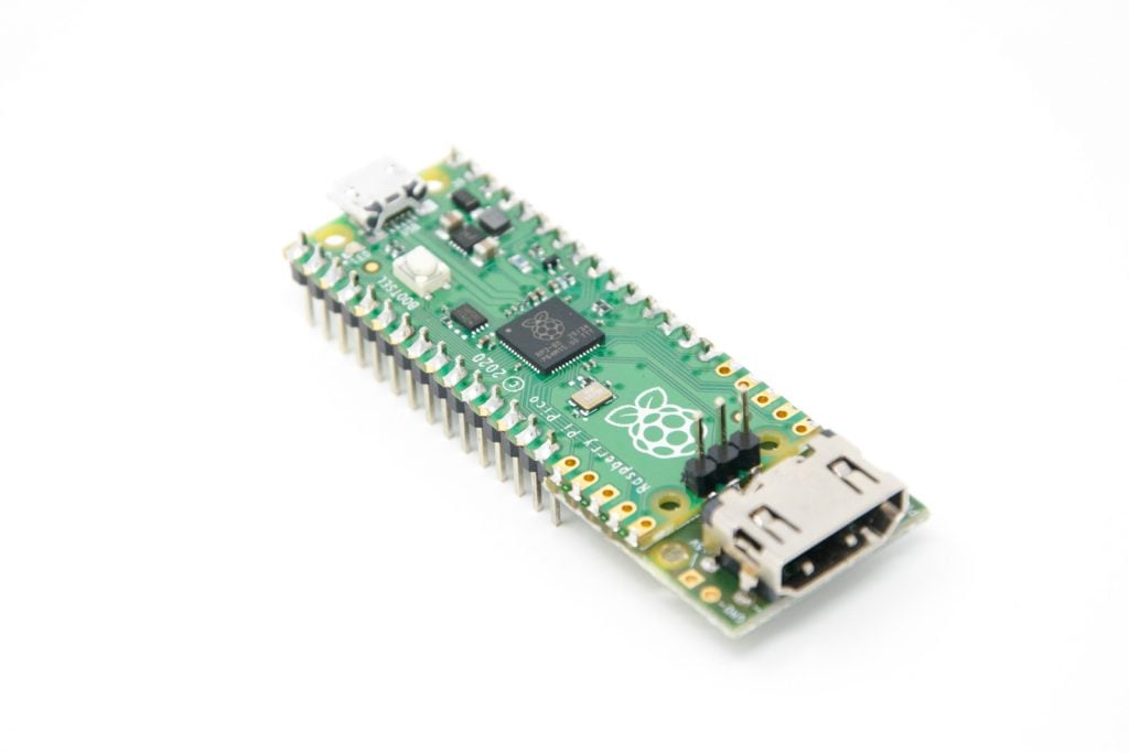
The Pico DVI Sock is an easy and low-cost solution to add digital video output to your Pi. It has been designed by Luke Wren (see description above). It is a DVI output with an HDMI connector. As HDMI is downward-compatible to DVI, you can use an HDMI cable to connect your Pico to HDMI displays:
Programming the Pico DVI Sock
TL;DR
You can download our picodvi-test.zip and get started playing around with the .UF2 example compiles in it. It also includes a PDF which gives you a step-by-step guide.
Code examples
Luke Wren provides code examples in his repository. However, to use them with the Pico DVI Sock, you’ll need to set the correct config to use. We’ll show you how in this mini-tutorial.
Install Prerequisites
sudo apt install cmake gcc-arm-none-eabi libnewlib-arm-none-eabi build-essentialClone PicoDVI repo from Luke Wren:
cd ~
mkdir pico
cd pico
git clone https://github.com/raspberrypi/pico-sdk
cd pico-sdk
git submodule update --init
cd ~/pico
git clone https://github.com/Wren6991/PicoDVI.git
To use the code examples with the Pico DVI Sock, you’ll need to set the correct pin config to use. Add the following line to common_dvi_pin_configs.h just before the first #ifndef
#define DEFAULT_DVI_SERIAL_CONFIG pico_sock_cfg
Building the examples
cd PicoDVI/software/
mkdir build
cd build
export PICO_SDK_PATH=~/pico/pico-sdk
make -j$(nproc)
Install the examples on the Pico
The built examples will be in the software/build/apps folder.
Press and hold the BOOTSEL key on the Pico, then connect the board to your PC using the microUSB connector. Copy and paste the appropriate .uf2 file you want to try – e.g. sprite_bounce.uf2 – to the Pico.
The Pico will automatically restart, and you should be able to see output on the HDMI connector (remember it’s DVI really :-)).
Download
You can download our picodvi-test.zip and get started playing around with the .UF2 example compiles in it. It also includes a PDF which gives you a step-by-step guide. If the sprite_bounce.uf2 example doesn’t work for you, try another monitor – possibly not all monitors are compatible with this video output.
If you’ve come so far, let us know in the comments how it worked for you & what project ideas you’ve come up with!
Purchase a Pico DVI Sock
Our sister page, buyzero.de, stocks the Pico DVI Sock in two variants:
- Pico DVI Sock only (for self-soldering) @ 6,58 € currently
- Pico DVI Sock on Pico, with pre-soldered headers @ 17,89 € currently
Sidenote: DBI & DSI displays
As a side note, the Raspberry Pi Pico Extras repository has placeholders for DBI (16 bit MIPI DBI displays – with data being passed in parallel) and DSI (MIPI serial displays), so we might see support for these displays in the future as well.
Any example of composite output with genlock?
I think composite output should be possible, but have not seen anything in the wild about that, yet.
As alternative to scanvideo, I’ve implemented another VGA/TV library for Raspberry Pico – ‘PicoVGA’, which I think is easier to use: http://www.breatharian.eu/hw/picovga/index_en.html
Thank you for sharing the info about your library!
Hey, can this HDMI be used as an INPUT and process the data.
the way it is programmed, and since the resistors act to limit the Raspberry Pi output signal – no.
possibly you could use an adaption of the design, with something which boosts the signal level instead of lowering it / and of course adapted code for the outputs to work as inputs, to be able to process the video data inside the Pico.
A few practical tips though. Thanks to silicon lottery, your particular unit may not overclock proportionally the gpu and the cpu part the same as well. So, if you don’t need faster graphics, don’t overclock its GPU. This increases your chance to overclock higher and have a stable system. Also lower power consumption and less supply current means better stability. Raspberry Pis with 4 CPU cores may hit a power delivery wall when loaded with all 4 cores active. The integrated PMIC (power management IC) may not supply the needed current for all of the cores, and turn itself off for a short period of time, thus rebooting the Pi. Cool the PMIC too. Don’t overvolt at max if you need all-core load (kernel compiles, heavy number crunching etc). Here we have a RPI4 which can run at 1850MHz with all cores active with over_voltage=2, but with higher over_voltage=3, it reboots when loaded. Higher over_voltage means also higher current and the PMIC circuitry has limited output current. The hotter the PMIC and its surrounding inductors, the less current it can supply. This is a limitation of the PMIC chip, not the BCM chipset. So, if you encounter occasional reboots under heavy load, it may be the overheating of the PMIC. If your Pi locks up, it won’t be this particular problem, but perhaps silicon lottery loss. Underclocking a GPU part may be an interesting way of increasing overclockability (more stable system), but AFAIK, older Raspberry Pis had L2 cache tied to the GPU, so underclocking it may slow the CPU too. I’ve documented how the PMIC of Raspberry Pi 4 heats – all other chips being cooled directly to a heatsink. The view is from an underside, i.e. you see the heated PCB. Lower left corner is the PMIC.
Thank you very much for these practical tips!
Hi,
Myself a noob here.. Can anyone provide a schematic for a cvbs display output. And any necessary change to the source code?
Sorry, no idea for the cvbs
Hello
Thanks for the nice post. I’ve read it from its beginning to almost its end 😉
However I’ve got some noobish questions:
1. RPi Pico has got PWM. Is it possible to use single pin with PWM to output analogue signal to feed to VGA pins? so less pins will be used. Also simpler and small circuits.
2. Is it possible to get Analogue AV output from RPi Pico again using PWM, maybe? I think most TVs support that. Perhaps using a module like https://thecaferobot.com/store/pub/media/catalog/product/cache/14d1897c7f1bd4f35a7de1523300314a/l/c/lcd-01-057-1.jpg available in a local store I’ve got access to. However the picture I’ve sent is a module for Arduino but it should be possible to use with Pico as well, I suppose.
3. If one wanted to go with VGA or DVI in combination with Pico, is it possible to not use those helper VGA or DVI boards? Because those are not available in my region to buy one and my skills are not good enough to create one myself.
1. PWM Pins will probably not have the timing precision you would like to have for video output (this is why we use PIO which has very precise timing). But why not try it 🙂
2. I assume that it should be possible to generate an Analogue AV output from the Raspberry Pi Pico. I doubt that the PWM will be “enough” for this (would be happy to hear anyone with more experience chime in on it!).
note that PWM is simply switching the signal on and off, while the resistor ladder used in the VGA board for example gives continuous signal levels. So for the PWM solution to work it must operate at much higher frequencies than is required for the actual signal. I’m also not sure how external hardware would react to the signal being PWM’d instead of a continuous analog signal.
Possibly it could be smoothed out using a very small capacitor, for which you would need to take appropriate calculations.
3. the helper VGA / DVI boards contain what is necessary (mostly resistors). You can look at the schematic and build your own setup on a breadboard possibly, I’ve seen someone do it for VGA.
That being said, we do ship internationally:
https://buyzero.de/products/raspberry-pi-pico-vga-audio-sd-expansion-board?variant=39412666335412
Pico DVI Sock @ buyzero.de shop
Great info. Thanks.
Also found this: Composite video out on Raspberry pico
http://www.breakintoprogram.co.uk/projects/pico/composite-video-on-the-raspberry-pi-pico
I managed to build the picoDVI from Wren6991 and integrate it with a triple ADC to scan RGB 15Khz (640×240).
In the 320×240 which just uses one core, the other is left alone to receive HSYNC /VSYNC interrupts and prepare dma transfers without hassle, but on 640×480 the 2 cores usage is blocking the system to work properly.
Since I do need half the lines, is there a way to have an always prepared black line for odd lines? with that I release one core for my dutties.
I don’t think you need to send any blank lines. You send all the odd lines, send a vsync signal with an extra half line, and send the even lines. Do some research into “interlaced video sync pulses”.
Does anybody know how to load videos made by myself rather than the example ones? Thanks in advance!
I’m interested in using it for an unique audio visual display purposes. Please, can anybody tell me:
Can you power the Pico through the HDMI cable, even if it’s on time broadcast side of the cable?
Can you set to Rec2100 colorspace (rec 2020 HDR colorspace)?
Is it possible to hook up extra lines to the HDMI, to send audio (and rec2020/HDR signaling)?
Can you output video through one of the USB video formats (video from unchanged Pico through a USB to Pico adaptor)?
Using the Pico wireless, can it do Miracast?
Can a regular bitmap video mode be done, and manipulated for game graphics with left over cycles?
Seedstudio does a mini RP2040 board. Can the HDMI interface board and software, work on that. They also have a RiscV version with wifi, so it would be good if it could recompile for that.
https://www.seeedstudio.com/XIAO-RP2040-v1-0-p-5026.html?queryID=31d59a67f7c148df996ba9c1bb7563e3&objectID=5026&indexName=bazaar_retailer_products
I am interested in gaming applications, like gaming watch use.
Any JavaScript minimal viable run time platform put there?
Sorry a lot to ask, but
Most interesting.
Thanks you.
Can I use your card along with Geoff’s MMBasic interpreter? Are there any hardware limitations on my programs due to your card?
Great minds think alike, I have been thinking along these lines too! I have already built the Raspberry Pico based MMBASIC computer with VGA output, and it’s nothing short of fantastic! However the DVI-D (Pseudo HDMI) output takes the graphics capability to a new level! Of course MMBASIC doesn’t have to fully exploit the higher colour depth or resolution, but operating at 640×480 with say 64 colours would be pretty noice.
Now with that said, I foresee two immediate problems.
1. The VGA solution also uses the PIO pins, and then one of the cores is used for sprite management, frame buffering etc. I believe. At the very least there will be a code change required, at least to replace the VGA PIO implementation. As an API, I will be surprised too, if the interface between PIO (VGA) and the framebuffer core code is the same as the DVI PIO solution, but I may be wrong. Anyway, there will have to be a code change.
2. RAM. There’s not enough of the stuff, so higher res and higher colour depths will be a problem. But I think I have a fix. Use external PSRAM, and perhaps use one RP2040/Pico as the “GPU” and it has its own dedicated PSRAM connected. It then talks to a secon RP2040 that provides the “CPU” or brains of the system, running MMBASIC, and it can manipulate/move graphical assets around by instructing the GPU with minimal overhead (say over I2C link). I want/need this 😉
64 euros for the “Raspberry Pi Pico VGA Audio SD Expansion Board”? One would better use a zero…
Pimoroni has a less expensive one (30 €), but still a lot. The DVI Sock only costs a few euros …