CircuitPython, Adafruit Feather RP2040, and I2C
As you probably guessed by the title, this article discusses CircuitPython, the Adafruit Feather RP2040, and the I2C communication protocol.
The RP2040 has two I2C controllers – good for example, when you want to run two I2C devices with the same I2C address.
In my test setup, I have an Adafruit Feather RP2040 microcontroller board, and have attached two of our BME688 breakout boards – one using the pins SCL + SDA and one using A1 (for SCL) + A0 (for SDA).
I am using CircuitPython in version 7.0.0, which you can download from here.
Furthermore, I’ve installed all of Adafruit’s libraries to the lib folder on the Feather RP2040. (The Feather RP2040 has enough space on it’s Flash to enable this)
You can download these libraries in the Adafruit CircuitPython Bundle here. (I downloaded adafruit-circuitpython-bundle-7.x-mpy-20211123.zip)
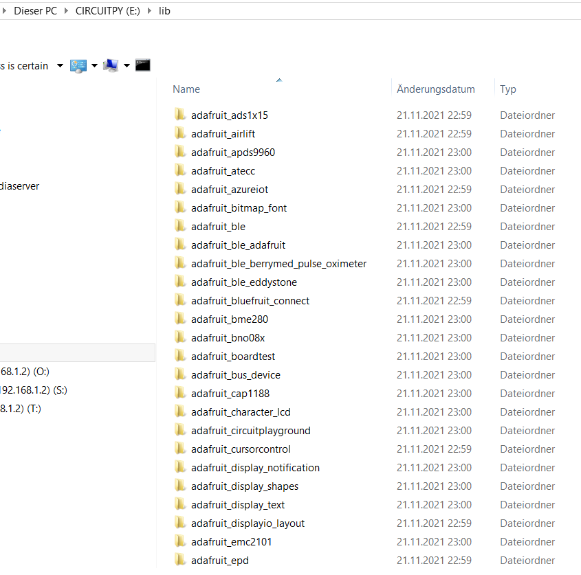
Note: to install these libraries simply copy them to the lib folder on the CIRCUITPY “drive” which is mounted on your computer. You will of course have to copy only the libraries, not the examples and other stuff.
The big advantage in using Adafruit’s stuff is that you get a ton of examples which cover many popular chips, and you can very easily start with it. There are things like driving a microSD card using SPI, reading an RTC, and reading from the BME680 sensor.
Testing I2C in CircuitPython
I’ve got the following setup, as I want to drive two devices independently of each other (which happen to have the same addresses in this case):
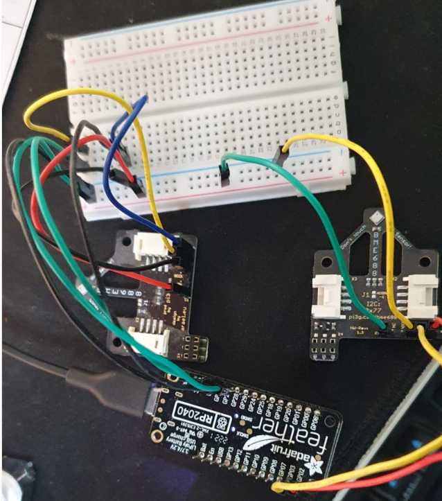
Note that our BME688 breakout boards already include Pullups for SDA and SCL. (You need pullups on SDA and SCL).
Note 2: Our BME688 breakout board has the option to change the address, so this scenario is meant for demonstration purposes.
In order to drive through both pin sets sequentially (to discover the devices), I’m using the following code:
print("Scanning SCL / SDA")
i2c = busio.I2C(board.SCL, board.SDA)
# a scan
i2c.try_lock()
print(i2c.scan())
i2c.unlock()
i2c.deinit()

print("Scanning A0 / A1")
si2c = busio.I2C(board.A1, board.A0)
# a scan
si2c.try_lock()
print(si2c.scan())
si2c.unlock()
Note: the i2c.deinit() is key to this particular example working! (because SCL / SDA and A0 / A1 have both the same hardware I2C peripheral – see below).
This should output the following:
Scanning SCL / SDA
[119]
Scanning A0 / A1
[119]
Here, 119 is decimal for hex 0x77 – which is the address of our BME688 breakout board in the default state.
Both boards are seen, sequentially in the individual scans.
The problem is that we want to use them simultaneously.
Running two I2C buses simultaneously on the Adafruit Feather RP2040
CircuitPython supports both hardware controllers (SDA0/SCL0 and SDA1/SCL1). You do not need to set any configuration (which controller you want to use, or how to mux the pins) – this is taken care of by busio for you.
You need to pay attention, though, which pins you use, as the pins will provide only one of these buses in each case, and if you happen to choose conflicting pins, you will get ValueError: I2C peripheral in use .
If you want to use “conflicting” pins, fo rexample SCL / SDA (which have SCL1 and SDA1) and A0 / A1 (which also have SCL1 and SDA1), you will need to bitbang one of the ports:
Here’s how to scan this pin configuration without calling deinit():
import board
import busio
import bitbangio
# https://circuitpython.readthedocs.io/en/latest/shared-bindings/bitbangio/index.html

print("Scanning SCL / SDA - main I2C")
i2c = busio.I2C(board.SCL, board.SDA)
# a scan
i2c.try_lock()
print(i2c.scan())
i2c.unlock()
# no need to call deinit here!
#i2c.deinit()

print("Scanning A0 / A1 - secondary I2C [bitbang!]")
si2c = bitbangio.I2C(board.A1, board.A0)
# a scan
si2c.try_lock()
print(si2c.scan())
si2c.unlock()

# we also do not need to call deinit here
#i2c.deinit()
We are using bitbangio to drive a secondary I2C. In my case the secondary I2C is used for an internal purpose (for a port expander), and quite likely can do with a lower interface speed.
Note: you are not able to choose the I2C peripheral which is routed to the pins in software – if you need a different peripheral, you need to use different pins.
Troubleshooting I2C errors
ValueError: I2C peripheral in use
If you are using busio.I2C for both ports: Check if you are already using the same hardware I2C peripheral – and whether you need to reassign your pins.
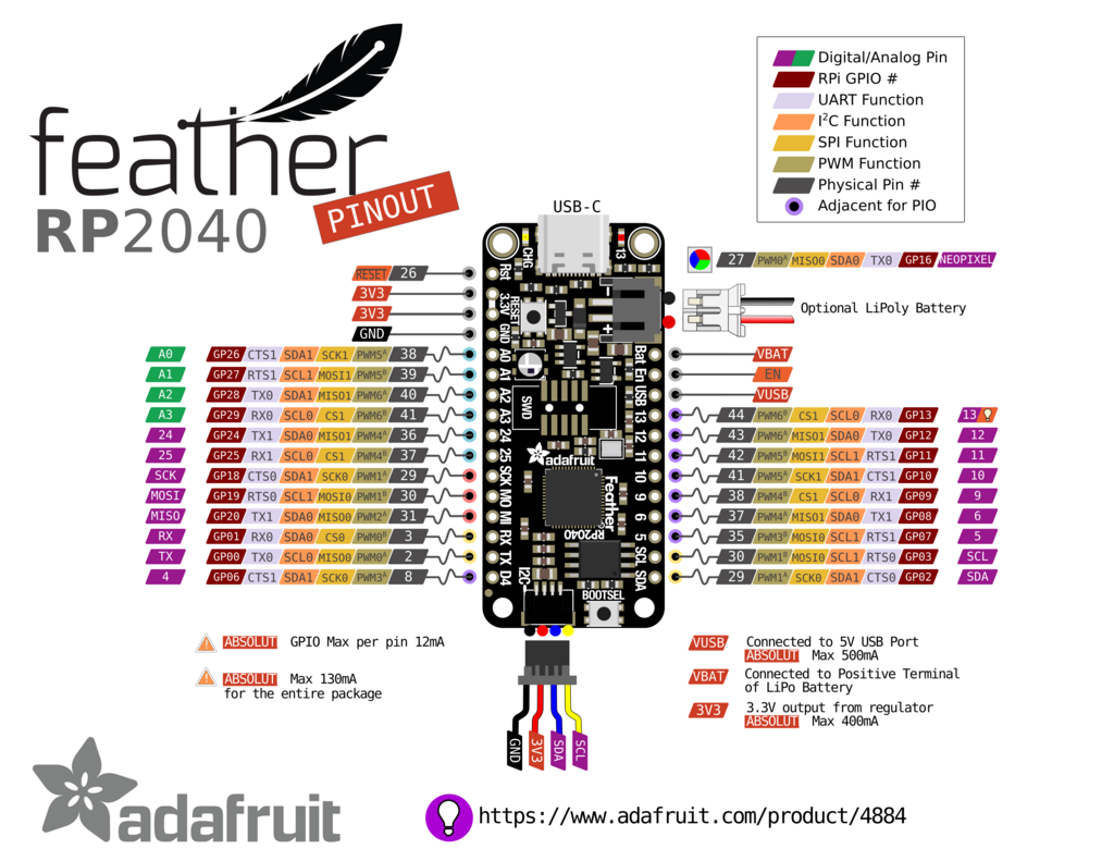
For example, both SCL and SDA , and A0 and A1 share the same hardware I2C peripheral (SCL1 / SDA1 – see the Adafruit Feather RP2040 pinout picture in this article).
In case you do want to use the same pin setup, you can use bitbangio to “create” an additional software-controlled I2C port. The downside of this is lower speed for this software-I2C port, and a higher CPU load.
RuntimeError: No pull up found on SDA or SCL; check your wiring
If you get the following error
RuntimeError: No pull up found on SDA or SCL; check your wiring
then you should put pullup resistors between 3V3 on the board (the 3.3V pin) and respectively your SDA and SCL pins. These are required for normal I2C operation (the devices pull down the I2C pins to communicate, the default / idle state on the bus is high) – and are not included on the Adafruit Feather RP2040. They are included on many Adafruit peripherals, and on peripherals of other companies (like, again our own BME688 breakout board).
If you don’t know what a pullup is: this is essentially a resistor between the pin in question (e.g. SDA) and the 3.3 V supply pin. It does not need to be terribly precise. You should start out with 10 kOhm resistors, if that doesn’t work, possibly try a 1 kOhm resistor for a “stiffer” pullup.
TimeoutError: Clock stretch too long
Check if the chip you want to talk to is powered properly.
Misc. notes
- The Adafruit Feather RP2040 has a NeoPixel LED on it. NeoPixels use a proprietary protocol, they do not use I2C.
- The Adafruit CircuitPython Community Bundle has a couple additional drivers
- There is a DebugI2C Helper
- The support matrix will show you which modules are supported on your board (e.g. the Adafruit Feather RP2040)
References / Resources / Links / Further reading
- Adafruit CircuitPython Bundle (libraries for CircuitPython)
- CircuitPython Busio documentation
- CircuitPython Board documentation
- CircuitPython on the RP2040 documentation
- CircuitPython I2C Essentials
Want to learn more about I2C? Check out our article on it here.
Thank you for a helpful article! I have two suggestions:
1) One cause for the “no pull up found” error (which is what brought me here) can also be caused by a dumb mistake: having a loose wire! This happens to me all too often because I am using Stemma connectors which are a little finniky.
2) I think your example code is a little confusing, in that I think it could/should have started with the simplest case wherein you use the two available I2C controllers, such as
i2c = busio.I2C(board.SCL, board.SDA)
…
si2c = busio.I2C(board.A9, board.A6)
The methods you use after that are of course still valid and useful!
/rob
Thank you for your thoughtful comment, Rob! Loose wires are like the “is it powered?” of the computer support world 🙂 Better to check than to spend hours debugging
Thank you for this article.
I’m migrating from Raspberry Pi Pico and have been looking for something like this!
Awesome!