SPI – The Serial Peripheral Interface
SPI means Serial Peripheral Interface. With SPI you can exchange data blazingly fast between two devices. And you only need four wires.
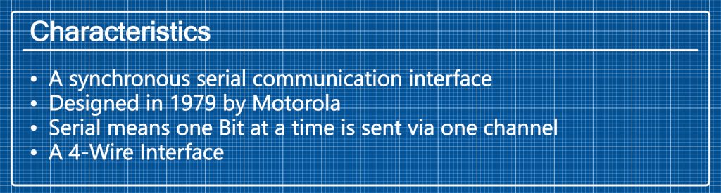
SPI Characteristics
The serial peripheral interface is a synchronous communication interface for short distances. Synchronous means that the data is sent in form of blocks or frames and the the two devices are synchronized using a clock. It is a serial interface so the devices send one bit at a time (unlike parallel communication). One of the devices is the “Master” and dictates the clock cycle. The other device is the “Slave”. Usually the communication is in full duplex mode. Hence both devices can send data, even at the same time.
Wiring
You only need four wires for the connection so it is very easy to set up.
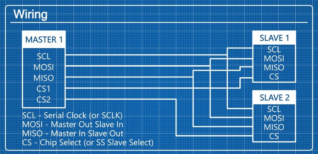
There are four pins that you need for an SPI connection are the Serial Clock (SCL or SCLK), the Master Output Slave Input (MOSI), the Master Input Slave Output (MISO) and the Chip Select or Slave Select pin (CS or SS).
Hook up the corresponding pins on the Master and Slave devices.
One Master device can connect to multiple Slave devices, as long as it has enough chip select pins. The Master controls which Slave device receives the data by setting the corresponding chip select pin to LOW or HIGH.
The Raspberry Pi 4 has 7 SPI busses . If you want to know how to access the SPI busses 1 to 6 then leave a comment below.
Let’s have a look at the SPI bus 0.
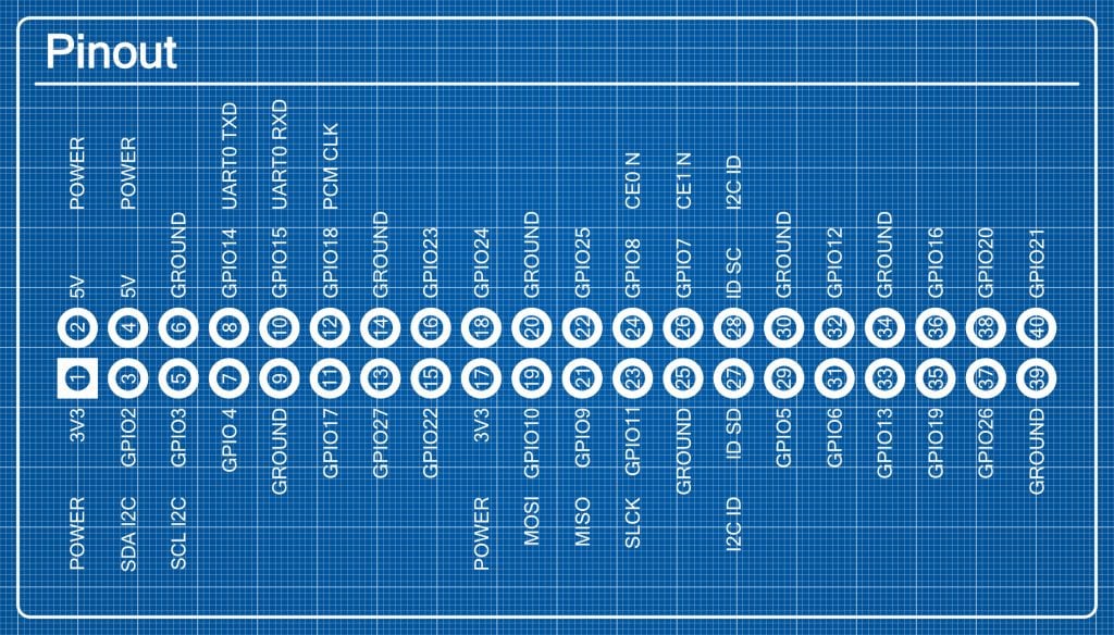
As you can see in the pinout graphic above pin 23 is the SCLK pin on the Raspberry Pi. MISO is pin 21 and MOSI is pin 19. The bus 0 has two CS pins which are pins 24 and 26.
If you want to use the bus 0, make sure to enable it first.
Execute the command
sudo raspi-configThen select 3 Interface Options and click I4 SPI. Finally press Yes and Ok to enable SPI.
SPI Modes
There are four different data transmission modes that you should be aware of. They differ in clock polarity and clock phase.
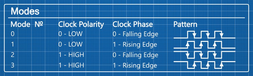
Both can be either 0 or 1. Regarding clock polarity, a 0 means a LOW idle state and a 1 means a HIGH idle state. A 0 clock phase means that data is sent on the falling edge, while a 1 means that the data is sent on the rising edge. Before they can send data, the Master and Slave have to agree to one of the four modes.
Advantages
The biggest advantages are the high speed, easy hardware and software set up and low power requirement.
Disadvantages
The serial peripheral interface is not really extensible in range and number of devices since the Master neads a chip select pin for each device. Also there is no hardware Slave acknowledgement, so the Master does not know if the data is recieved by anyone.
Use cases
Most SPI devices are embedded devices or LCD-Displays. In general, it is used in areas where few devices and fast data transmission are required.
It allows the Raspberry Pi to interface all kinds of sensors and devices. Nearly all Raspberry Pi compatible devices use the SPI or the I2C interface.
SD cards use the SPI interface as well so even the SD card reader on the Raspberry Pi has some internal MISO and MOSI pins.
[…] If you’d like to learn more about SPI, by the way, we have an article on it here. […]
[…] SPI – The Serial Peripheral Interface […]
[…] Naveen explains, the connection between the Nano and the TFT display is based on the Serial Peripheral Interface (SPI). Meanwhile, the joystick and buttons are connected via the Inter-Integrated Circuit Bus […]
[…] SPI – The Serial Peripheral Interface […]
[…] Anzahl der Geräte nicht wirklich erweiterbar, da der Master für jedes Gerät einen Chip Select Pin […]
Es gibt die Möglichkeit Geräte per Daisy-Chain aneinander zu reihen. Dadurch wird nur ein Chip-Select benötigt. Allerdings muss man wissen wie viele Geräte in welcher Reihenfolge am SPI angeschlossen sind, so dass man die Datenpakete als Stream passend zusammenbauen kann. Die Geräte werden so verschaltet, dass MISO des vorherigen Geräts am MOSI des nachfolgenden Geräts angeschlossen wird. MISO des letzten Geräts wird dann tatsächlich mit dem Master-Gerät verbunden. Durch diese Technik werden die Daten aller Geräte auf einen Rutsch gültig gestellt, wenn nach dem Senden des Datenstreams der Chip-Select aktiv geschaltet wird.