Build a Virtual Reality Glove
If you want to learn more about VR than this is the coolest project that you will find. In this article, we will show you how to build a programmable Virtual Reality Glove.
The glove is based on a Raspberry Pi Pico, a MCP3008 ADC and five flex sensors that you can even build yourself!
What you’ll need
Here is a list of things that you need for this project
- Raspberry Pi Pico
- MicroUSB / USB Cable
- MCP3008 ADC
- Five flex sensors
- Some wire or jumper wires
- Five 330Ω resistors
- Soldering equipment (optional)
- Breadboard (optional)
If you prefer a video guide then we got you covered.
Build your flex sensors
Since most flex sensors cost around 10$ a piece, it is way cheaper to build them yourself.
This Video shows how to do that, although we made some changes to improve the performance.
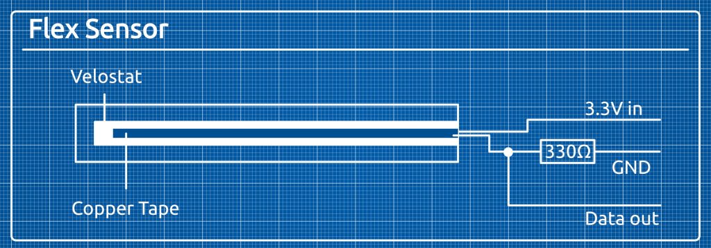
Substitute the internal paper strip with velostat and the aluminum foil with copper tape. Also make the strips very thin (around 1 mm for the copper strip and 2mm for the velostat) to increase the resistivity of the sensor. Increased resistivity leads to higher resolution.
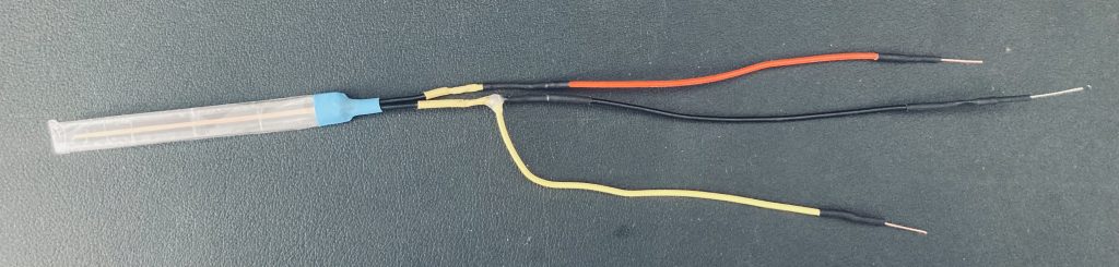
Also you can solder the voltage divider circuit to remove some wires from the breadboard. Solder a red wire to one end. The read wire will be the positive contact. Solder a yellow wire to the other end. After the yellow wire you need to connect a 330 Ohm resistor which will be connected to ground.
In my case the resistor is at the end of the black wire and I insulated it with some heat shrink tubing.
The yellow wire will serve as our data cable.
The voltage divider circuit
A voltage divider circuit is commonly used in the embedded realm. It consists of two resistors in series with an output connection in between.
It outputs a fraction of the input voltage and the precise amount depends on the resistivity of both resistors.

Wiring
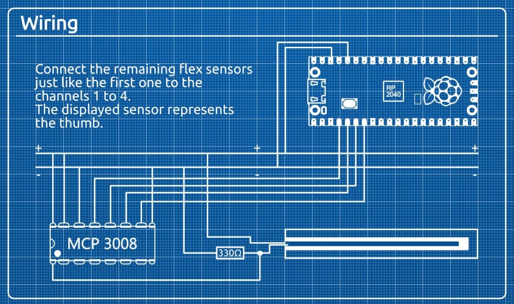
Connect your MCP3008 to your Raspberry Pi Pico according to this graphic.
We have a step by step explanation in our video.
Connect the flex sensors like the one in the graphic. The eight pins on the left side of the MCP3008 are the channels 0 to 7 (top to bottom). Connect the data wire of the flex sensor for the thumb to channel 0, the index finger to channel 1, the middle finger to channel 2, the ring finger to channel 3 and the pinkie to channel 4.
If you want to change the order or add additional sensors you need to change the software on the Pico.
Set up the VR Glove software
Set up the Pico
In this set up the MCP3008 converts the analog singal from the flex sensor to a digital one. The Pico then reads the data and sends it to a Windows PC via USB Serial.
For the Pico we will use Circuit Python as it provides a MCP3008 module that really facilitates things for us. To install Circuit Python on your Pico, download the .uf2 file from the Official Pico Circuit Python site.
Connect your Pico via USB while holding the BOOTSEL button. Then drag and drop the .uf2 file onto the Pico. The Pico will remount as CIRCUITPY.
Donwload and extract the mcp3xxx Circuit Python Library that contains -mpy- from this site.
It contains a lib folder, that you need to copy onto the Pico (which is now the CIRCUITPY drive).
Then download the code.py script from our GitHub repository and copy it onto the Pico.
Now whenever you power up your Pico (without holding the BOOTSEL button) it will read the first five channels from the MCP3008 and send the data to the USB Serial.
Set up Blender
The next step is to install Blender for your OS. This example was tested for Windows, but it should work on other operating systems too, with a few minor modifications.
We need the PySerial Python module to read the Serial Data from the Pico in our Python script. Blender comes with it’s own Python version. Make sure to install PySerial there.
Check out our video to learn how to install PySerial in Blender on Windows.
Now download the hand.blend file from our GitHub and open it in Blender.
You Should see a 3D hand on the left and a Python Script on the right. In line 73 a “Serial” object is created. You need to pass the name of your USB Serial Port to the contructor (which in my case was “COM4”).
Conclusion
Want to see other projects that you can make with a Raspberry Pi Pico?
Check out our Paragon Projects series by clicking on this button:
What will you do with your new Virtual Reality Glove?